But what if you have wired IP cameras and want to achieve the same result – block PoE IP cameras from accessing the Internet? Fear not, all you need to have is any one of the following:
[easyazon_link identifier=”B086967C9X” locale=”US” tag=”vueville.com-eaz-20″]Unifi Dream Machine Pro (UDM Pro)[/easyazon_link] which is an all-in-one device that combines a managed switch and hardware firewall, OR
a Unifi managed switch and separate firewall, such as the [easyazon_link identifier=”B01MU3WUX1″ locale=”US” tag=”vueville.com-eaz-20″]Unifi Switch 8[/easyazon_link] & [easyazon_link identifier=”B00LV8YZLK” locale=”US” tag=”vueville.com-eaz-20″]Unifi USG firewall[/easyazon_link] combo.
Assuming you have already created a VLAN as described in Step 1 of this tutorial, here are the steps to group or assign wired Ethernet devices into a VLAN:
[wpsm_divider top=”20px” bottom=”20px” style=”clear”]
We get questions and request for advice from our readers regularly through email and social media. The questions we are asked and their answers may potentially be valuable to others too, so we have decided to share the best ones on the blog.
Today’s question comes from Brad.
I am looking into a camera system for outdoor security. My internet access at home is a wireless jetpack only. Is there a system that can connect to the base station without an Ethernet cable or an hard cable ? I want the ability to view from my phone.
Every conventional wireless NVR system I’ve seen would connect to your router through an Ethernet cable. I assume by wireless jetpack you mean one of these devices which don’t have an Ethernet port.
If you want a DIY camera system like mine or if you want a fully-fledged NVR kit with 24/7 recording, then the easiest option is to connect the NVR via Ethernet to a [easyazon_link identifier=”B010S6SG3S” locale=”US” tag=”vueville.com-eaz-20″]wireless extender like this one[/easyazon_link] which has a physical Ethernet port. The wireless extender then connects to your jetpack’s Wi-Fi network. Neat and efficient. You can also plug an [easyazon_link identifier=”B07PFYM5MZ” locale=”US” tag=”vueville.com-eaz-20″]unmanaged 8-port switch[/easyazon_link] into the Wi-Fi extender and then plug all your wired Ethernet devices into that switch (including the NVR) 🙂
If you have an old WiFI router lying around, you can put it in ‘wireless bridge’ or ‘repeater’ mode to achieve the same results as above for free (see Asus example). I have this setup in one part of my home where my main Wi-Fi doesn’t reach.
If you don’t need 24/7 recording and need only 1 camera (or less than 4), I would just get a wireless IP camera like this one from Reolink which doesn’t need an NVR – they are capable of independent operation. They can connect to your wireless jetpack through Wi-Fi and then you can see all your cameras in one app on your mobile phone or PC. There are no subscription fees at all. Motion detection clips are saved to the SD card onboard, and you get emails with photos or 30 sec video clips. So a very cheap option without a 24/7 recording feature.
Do you have a question for us? Contact us and fire away!
It’s been quite a while since we’ve had a Reolink IP camera review here at VueVille. We already reviewed the 5MP Reolink RLC-422 dome, and today we have the bullet camera version named the RLC-511 also with optical zoom. The cameras seem to have similar sensors and share other features too.
The RLC-511 comes in a very professional-looking retail box. The camera’s main features are highlighted, as are the mobile app and the 2-year limited warranty.
Every Reolink camera I have reviewed has come very well-protected and the RLC-511 is no exception.
Box contents:
RLC-511 Zoom IP camera
Screws, rawl plugs and an Allen key
Waterproof sleeve for Ethernet cable
1 metre blue network cable
Software CD
Installation guide with photos
Mounting hole template
Surveillance sign
Specifications
[table id=68 responsive=”scroll” /]
Design
The RLC-511 is a bullet-style camera and has a boxy-look reminiscent of far more expensive Hikvision bullets. Compared to the [easyazon_link identifier=”B08F568BH1″ locale=”US” tag=”vueville.com-eaz-20″]RLC-510A[/easyazon_link], this camera is a lot bigger than you might expect. That’s because its got a 4x optical zoom.
The RLC-511 has a metallic body. The fit and finish is very good and as with other Reolink cameras I have reviewed, it feels like a camera that is far more expensive than it is.
The back of the camera houses the microSD card slot, secured by two screws. The way it is located means that there’s no access to the slot after installation. And that’s exactly how you want it in a security camera – a burglar shouldn’t be able to steal the microSD card easily.
The motorized vari-focal lens on the RLC-511 goes from a focal length of 2.7 – 12 mm with auto-focus. The 1/2.7″ 5 Megapixel Progressive Scan CMOS sensor is par for the course, this is not a camera that specializes in low light performance (for that check out the [easyazon_link identifier=”B07B16DFMB” locale=”US” tag=”vueville.com-eaz-20″]Hikvision Darkfighter[/easyazon_link] series)!
There are 24 IR LEDs arranged in a ring shape around the lens. None of them are obscured or blocked in any way. A plastic shroud protects the lens from rain or snow.
The day/night sensor for the auto IR cut filter is placed right below the lens.
All the cabling comes out of the base and can go conveniently into a junction box or through the wall. As usual with Reolink cameras, the cabling consists of a pigtail with the following connectors:
RJ-45 ethernet port
12V power input jack
A reset push button
Just like the Reolink RLC-423 PTZ, the reset button of the RLC-511 is not on the main body of the camera. Apart from eliminating an ingress point, it means nobody can reset the camera unless they get to the hidden reset button which is probably inside the wall or the soffit! This is much better than many other cameras such as Hikvision’s which have the reset button externally on the camera body itself.
On the bottom, there is a sticker with the QR code for the mobile app setup and login details. I recommend removing this sticker before installing the camera outdoors for security purposes. Otherwise anyone will be able to load up the camera admin page, and if you haven’t changed the default admin and password shown next to it, you are in big trouble!
You can also spot the microphone hole on the underside.
Installation
Bullet cameras are the easiest type of IP cameras to install, and Reolink makes their installation process also super easy.
First I used the included Allen key to loosen the steel arm of the camera base. I did this by turning it in the direction of the unlock symbol engraved into the base.
This is required to access the three screw holes of the base one by one as you screw them in.
I then used the included screws to fix the RLC-511 to my usual test location, a wooden soffit.
After pointing the camera in the general direction of the scene, I tightened the steel arm again in the direction of the lock symbol.
Hardware setup
The RLC-511 supports Power over Ethernet (PoE) which is my recommended way of powering IP cameras. Using just a single Ethernet cable, you can send both data and power to the camera using either a PoE switch or a PoE injector.
Since this is a bullet camera with motorized varifocal lens, you cannot adjust it manually.
A typical fixed lens camera needs around 7W power, but the motorised lens of the RLC-511 means that it needs a little more power, up to a maximum of 10W. This is still within the 802.3af spec, so both my [easyazon_link identifier=”B01BW0AD1W” locale=”US” tag=”vueville.com-eaz-20″]TP-Link PoE switch[/easyazon_link] and [easyazon_link identifier=”B01DKXT4CI” locale=”US” tag=”vueville.com-eaz-20″]Unifi Switch 8[/easyazon_link] are up to the task of powering the camera over PoE.
If you want to use the included waterproofing connector, you will have to remove the RJ-45 plug on the Ethernet cable and re-crimp it once it has been passed through the waterproofing connector. My install location is sheltered from the elements, so I didn’t bother with this.
Software setup
Most manufacturers ship their cameras with static IPs by default – for example Hikvision and Dahua. In most cases the camera will not have the same network settings (like sub-domain) as your network.
This means that you cannot access the camera unless you change the camera network settings to that of your network. You are expected to do this using the manufacturer’s camera finder tool, like SADP in the case of Hikvision.
While this static IP method has a lot of security benefits, most home users would find it much easier if the camera manufacturer used DHCP as default. This way, the camera would automatically be configured to use your network settings and be ready to use.
As with all the Reolink cameras I have tested, this is exactly the case with the RLC-511: Reolink has DHCP enabled by default.
There are quite a ways to start using the RLC-511:
Use the Reolink mobile app
Use the Reolink desktop client software
Use any camera monitoring software such as BlueIris
Use a mobile security camera app such as tinyCam Monitor Pro
The Reolink setup guide for this camera suggests the first two methods – Access the camera by smartphone and access the camera by computer.
I have tried option 1 with another Reolink before so I went with option 2 this time – setup through a computer. These are the steps I followed:
Step 2: Installed Reolink Desktop Client and installed it. Windows Defender identified it as a new app and asked me if I want to allow it Internet and LAN access. I allowed it to proceed.
Step 3: The app automatically identified the camera and logged in successfully, and presented me with the Live View screen.
Step 4: As I mentioned earlier, the camera has DHCP enabled by default but I like to assign my cameras static IP addresses. The main reason is that its easier to set up and access the camera form other devices without having to check each time what the IP address is.
Clicking on the setup gear icon and clicking through to Network > General allowed me to change it. This caused the Reolink app to add another camera to the list, with my new static IP address. It also then started complaining that it could not find the original camera with DHCP IP address. This was a bit tiresome so I disabled the ‘Add Camera Automatically’ option under app settings. No reboot was needed which is great.
Step 5: I then tried to access the camera from the new static IP address through Chrome. I logged in with the default login details. However since the camera admin site uses Flash and Chrome disables it by default, I just had to click on the “Get Adobe Flash player” button in the live view section and enable it in Chrome.
Step 6: I then changed the password for the admin account. I also created a new user and tried to delete the admin account for safety but like most IP cameras, the RLC-511 doesn’t support this feature.
Once you have the IP address, you can simply pop that into Chrome or Firefox to directly access the camera settings. You could also use the desktop client app to change camera settings if you don’t want to use the web-based admin panel.
You should change the password of the camera as soon as you can, especially worth noting as the camera doesn’t require you to nor remind you to do it.
Software features
I have a number of ways of accessing my camera live feeds – typically I use the tinyCam Monitor Pro app on my Android phones. But when I want to tweak camera settings, I use the built-in web admin page of the camera.
So entering the camera’s IP address into any browser that supports the Adobe Flash player will let you login to the camera. An HTML5 interface would have been better but Flash is far better than the NPAPI plugin that Hikvision still insists on using. Use Internet Explorer or the new Microsoft Edge, Chrome doesn’t support Flash anymore.
You can choose the video stream quality you want to see at the login screen, ‘Channel 1’ is called Clear and is actually the 5 Megapixel stream (unless you have changed the camera settings). The other options are Balanced (medium quality) and Fluent (sub-stream). These can also be selected once you are logged in.
Click on the ‘Get Adobe Flash player’ button, and click ‘Allow Once’ when the browser says the content is blocked. The live view should now begin.
Reolink calls the landing page the Preview page, but I like to call it the Live View page. On the left hand side you have the live view stream, and at the bottom clicking the play button lets you select between the video quality by switching between the Clear, Balanced and Fluent streams.
On the right hand side, there are three sections – Optical Zoom, Basic settings and Advanced settings. The basic and advanced settings sections are like a quick access area that duplicates the settings on the actual configuration page – accessed by clicking on the gear button at the top right.
The Optical Zoom section adjusts to the abilities of the camera. You can change the zoom and adjust the focus manually (see the zoom test in our video review).
The Basic Settings section includes OSD settings, video stream encoding and image settings. Remember you can also change all of these settings in the configuration pages. So The OSD page is pretty standard and lets you choose whether and where to show the OSD information such as day, date and time.
The Basic Settings is where you can set the video resolution, bitrate and frames per second of each of the Primary “Clear” stream (5MP default @30fps and 6Mbps) and the Fluent stream (640×480 default @7fps). Interestingly, the ‘Balanced’ stream is missing in the stream selection drop-down.
The Image section lets you adjust the usual image settings such as brightness, contrast, saturation, sharpness and also mirroring and image rotation.
The advanced settings tab is where you will find the rest of the video settings and the ones I was most interested in – exposure, backlight and noise reduction. Setting the Exposure to ‘Low Noise’ lets you control just the range of gain, ‘Anti-smearing’ lets you control only the range of shutter speeds and manual lets you select both the gain and shutter speed ranges. The range selection method is novel – it means the camera will automatically choose the optimum settings from the range you specify.
A new addition is the LED Light option, which wasn’t available on the RLC-422 or the RLC-423.
I didn’t see an option to change the i-frame interval. This is a bit strange as it is a setting that I would have expected to find. Why is it important? The i-frame setting specifies how often the entire frame is captured and not just what has changed from the previous i-frame. So being able to control it is important for getting the right balance between network bandwidth utilisation and a high quality non-blurry video.
Now the full camera settings configuration page is accessed by clicking the gear icon at the top right of the Live View page. This lets you access video resolution, network, motion detection, email and push notifications, user control, and system maintenance settings.
Under the recording section, there are 2 tabs – encode and advanced.
While the camera support motion detection alerts, these are of the basic variety. There is no advanced motion detection such as line crossing, or intrusion detection on offer here. One of the best ways to reduce false alerts is by using these advanced motion detection methods, so bear this in mind if you are planning to use this camera not for 24/7 recording but motion triggered recording. I would use it only for 24/7 recording or to capture images and videos based on commands from my DIY home automation system.
You can adjust the motion sensitivity for the time of the day. For example, you can have a higher sensitivity during the daytime and a lower sensitivity at night to avoid false alerts. On the detection tab, you can draw motion detection regions.
The network settings section groups together port configuration, DDNS, FTP, and motion detection notifications.
There is a built-in NVR feature, so the camera can record motion detection clips to the on-board SD card, and even 24/7 a network/NAS drive.
Performance
I tested the RLC-511 at its default settings of 5MP resolution, 30fps and 6Mbps bitrate.
To optimise recording storage, I suggest setting the main stream to 5MP resolution @ 10fps, and increase the sub-stream bitrate:
The optical zoom function is the standout feature of the RLC-511. I found the zoom speed to be very similar to the [easyazon_link identifier=”B09DPSB9BL” locale=”US” tag=”vueville.com-eaz-20″]Reolink RLC-422 dome[/easyazon_link] (review) and the [easyazon_link identifier=”B095H2BBWZ” locale=”US” tag=”vueville.com-eaz-20″]Reolink RLC-423[/easyazon_link] PTZ (review). The autofocus is a bit sluggish just like the RLC-423 but at such an affordable price, I shouldn’t complain.
Video quality
The RLC-511 is a 5MP camera with a 1/3″ sensor, just like the RLC-422 dome. Daytime performance should be good, but the small sensor is not suited for ultra low light situations.
In my testing I found the daytime video to be similar to the RLC-422 dome. Crisp and much sharper than my 4MP Hikvision DS-2CD2542FWS-IWS as well as the 4MP Reolink RLC-423 PTZ. However it couldn’t compare with the 8MP Hikvision camera.
If the camera has one weakness, it is the speed of the autofocus. While the accuracy of the autofocus is pretty good, it does take a few seconds to re-focus after zooming in or out.
The real test of an IP camera is when the sun’s gone down and the lights are off. In my opinion, the night-time video quality is great with just a slight hint of noise. The RLC-511 uses 24 conventional IR LEDs arranged in a ring around the lens. While these are powerful, the ring arrangement does cause a noticeable flash-lighting effect when you are pointing the camera at a nearby wall or floor.
Mobile app
The Reolink mobile app is one of the best original manufacturer apps I have seen. Hands down it beats Hikvision’s rather poor efforts and runs circles around other brands’ apps.
I was able to quickly add the RLC-511 to the Reolink app on my phone, adjust the zoom level, and use the built-in NVR feature to access the recorded clips on the on-board SD card.
The RLC-511 works great with my favourite mobile CCTV app, tinyCAM monitor Pro.
Compatibility with QNAP QVR Pro
Adding the RLC-511 to QVR Pro was a breeze. It works well because QNAP officially supports this and other Reolink models. I created a motion detection trigger and event to test the reliability of the trigger and the pre-record and post-record features.
For this I also logged into the camera admin page and set up the motion detection zone – you can’t do this from the QVR Pro interface.
Motion detection was reliable and worked as expected. The QVR Pro client even allows you to control the optical zoom of the RLC-511.
You can also set up event recording of the main stream at the same time as 24/7 continuous recording of either the main or sub stream. This is great for getting those pretty pink markers on the timeline that you can jump to quickly.
Verdict
The RLC-511 is the best budget 5MP camera on the market with optical zoom. It has great video quality in the day and night, and is also capable of stand-alone operation with the microSD card slot and built-in NVR feature.
While the 5MP resolution is very good for a budget IP camera, other brands such as Amcrest are moving to 8MP cameras which have 4K resolution. I am looking forward to an 8MP version of the RLC-511.
What’s missing with all the Reolink cameras are advanced motion detection methods, and audio & alarm connections. The slow zoom and auto-focus is also a bit frustrating.
For those who need a 24/7 recording bullet camera with optical zoom, the ONVIF and RTSP support makes the camera very easy to integrate with compatible NVRs or a DIY NAS NVR. BlueIris users, note the lack of an iframe setting – this makes it tricky to get the camera to work as desired in BlueIris.
[review]
Where to buy
[easyazon_link identifier=”B08QV8T3D9″ locale=”US” tag=”vueville.com-eaz-20″]Check Price on your local Amazon site[/easyazon_link]
I started my DIY CCTV system with Hikvision cameras many years ago, but over time I’ve added quite a few Reolink IP cameras to my DIY CCTV system.
Hikvision has been probably the most popular non-retail brand whereas Reolink is a very popular budget-friendly yet brand. They are pretty much at opposite ends of the spectrum.
While enthusiasts might balk at budget brands like Reolink and Amcrest, I am a big fan of only spending as much money as needed on this hobby. You don’t need the most powerful IP camera everywhere in your home. So there’s a place and application for all types of IP cameras.
Having owned and used many cameras from both brands extensively, here’s my detailed take at Hikvision vs Reolink IP cameras and which one may be right for you.
A quick note: This article may contain affiliate links. If you click on one of these links and then purchase something, we may receive a fee. This does not cost you anything extra. Also note that Hikvision and Dahua do not consider certain platforms including Amazon as an authorized seller platform. So if you need warranty support please purchase from authorized resellers of Hikvision and Dahua products in your country.
Hikvision vs. Reolink – the Stories behind the Brands
Hikvision
Unlike Reolink, Hikvision is not a retail brand. They are an OEM and primarily cater to professional installers. They are not really interested in retailing to the general public. But their affordable DIY IP cameras with powerful motion detection features and great build quality attracted DIY-ers like crazy. That’s also the reason I bought my first IP camera, the Hikvision DS-2CD2032-I back in 2015.
A couple of years ago, they launched their retail brand EZVIZ. Confusingly, EZVIZ used to be the name of their cloud app as well. Anyway the EZVIZ models are dumbed down versions of the Hikvision cameras and are not worth spending any money on. What about HiLook? Same story. That’s why I am focusing on the main Hikvision brand.
The biggest concern I have with Hikvision is not so much about their cameras, but who owns the company. The Chinese government owns at least a partial stake in Hikvision. This creates a few ethical and moral quandaries that I won’t go into here – you know what I’m talking about.
If you live in the USA, there’s one more reason to avoid Hikvision cameras – the US government has recently banned the sale and import of new Hikvision products into the USA unless certain conditions are met. They are still being sold by their authorized retail seller BH Photo though. Of course, you can always get them from AliExpress as most of us have always done.
From a technical standpoint, you should treat any security camera the same way – with maximum suspicion that they may be ‘dialing home’ to their manufacturer’s own servers and leaking your data. So lock them down using Virtual LANs (VLAN) and strict firewall rules like I have in my DIY home security camera system.
Reolink
Reolink is the brand name of IP cameras manufactured by Reolink Innovation Limited (earlier known as Shenzhen Baichuan Security Technology Co., Ltd.). A few years ago, they launched the Reolink brand and seriously upped their marketing game. This push paid off handsomely with Reolink pulling off an upset in the budget IP camera market.
Apart from solid build quality, super affordable pricing, and totally offline operation, what I really like about Reolink is the quality of their apps and PC software.
8MP 4K IP Camera Duel – Hikvision DS-2CD2085G1-I vs. Reolink RLC-810A
In 2025, everybody’s selling 8MP IP cameras. 4K resolution is the buzzword and 8MP is what you need to get 4K video. So lets pitch an 8MP camera from each brand against each other.
Until 2021 Reolink didn’t have an 8MP model that was ONVIF compatible. But now almost all Reolink models support ONVIF and RTSP. So lets pick a camera from Reolink’s current lineup that represents the most common form factor of IP camera, a bullet camera with a fixed lens. Specifically the RLC-810A. The 8 in the model number represents its 8 Megapixel sensor.
Hikvision constantly refreshes their model lineup. The Hikvision model that’s widely available online and that is comparable to the RLC-810A in price is the DS-2CD2085G1-I (sourced from AliExpress).
Hardware features – Hikvision vs. Reolink
The size of the sensor has a huge bearing on the low light ability of a camera, whether it be a camcorder or a security camera. The larger the sensor, the greater its ability to gather light and so do well in low light conditions. So a larger sensor is the key to great low light performance.
But as you cram in more and more pixels into the same size sensor, they get smaller and smaller, which adds noise. Noise is the bane of low light video and reduces the detail that you can get out of your video.
The Hikvision model has the term ‘Darkfighter’ in its marketing material and that’s a hint at its strong low light performance. This is really due to the 1/2″ sized CMOS sensor whereas the Reolink has a 1/2.5″ CMOS sensor. Don’t get me wrong, the RLC-810A is a fine low light performer but the Hikvision definitely has the edge here.
Both cameras support Power over Ethernet (PoE). Both also have on-board storage in the form of a microSD card slot that can take cards of up to 128 GB capacity.
The cameras bodies are both made from metal but differing levels of ingress protection (IP67 for Hikvision and IP66 for Reolink). I am happy to see Hikvision have embraced IP67, they have always gone for IP66 for their outdoor IP cameras.
Neither have vandal protection (IK10), more expensive Hikvision bullets do have it these days.
The Reolink does have a built-in microphone, but Hikvision doesn’t.
Winner: Hikvision
Software features – Hikvision vs. Reolink
The three most important software features that I look for are ONVIF support, the built-in NVR feature, and the advanced motion detection features that help reduce false alerts. Why because if an IP camera has ONVIF and RTSP features, you can use it as a standalone IP camera or easily integrate it into a Pro-DIY type DIY NVR system like mine.
While Hikvision has always supported ONVIF and RTSP on all their IP cameras, Reolink supports it on most of their models (the battery powered ones and B model cameras don’t).
ONVIF ensures that your camera will work with standards-compliant gear from other manufacturers. This is why you can add a Hikvision or Reolink camera to your ONVIF-compatible NVR or DIY NAS NVR and integrate it into my smart home automation system.
RTSP allows even non-ONVIF equipment (such as software) to access the security camera’s video stream. Examples are video players like the popular VLC player or [easyazon_link identifier=”B004VD3YIM” locale=”US” tag=”vueville.com-eaz-20″]tinyCAM Monitor Pro[/easyazon_link] on Android.
The Hikvision has true 120dB Wide Dynamic Range (WDR) to help improve video quality in high glare situations. The Reolink has only digital WDR. This can make a difference if your scene has bright and dark areas, like a lamp that casts long shadows.
Hikvision cameras now support H.265+ which is a very efficient codec for encoding video streams. Reolink has moved on from H.264 and now supports H.265 but there’s still no H.265+ support. The difference you will see is in the file size at the same bitrate. You can benefit from H.265+ by increasing the Hikvision’s bitrate to the max 16Mbps and still enjoy bandwidth and storage requirements comparable to the Reolink at its max 8Mbps bitrate.
Motion Detection ability
The Reolink doesn’t have the wide array of advanced motion detection alerts that Hikvision has, such as line crossing, intrusion detection etc. which are all great for reducing false motion detection alerts.
On the other hand Reolink does have person, vehicle and even pet detection (beta for now). These are equally effective at reducing false alerts.
The Hikvision camera I have selected doesn’t have the AcuSense feature which reduces false alarms by ignoring birds, animals, lights and movement of trees.
Depending on what your specific needs are, you may find either camera suitable.
Hikvision gets the slight edge here if you are not interested in smart detection like vehicle/pet, and need the advanced methods such as line crossing/intrusion detection. Remember it can still do face detection as well.
Reolink gets the edge if you only care about person/vehicle/pet detection.
As part of a DIY NAS NVR system that uses Blue Iris or Home Assistant, both Hikvision and Reolink may fit the bill. Hey maybe get the best of both worlds and get 1 of each covering the same scene!
Winner: Tie!
Mobile app
There’s no contest here, the Reolink mobile app is miles ahead of the IVMS suite of Hikvision mobile apps.
Winner: Reolink
Warranty – Hikvision vs. Reolink
Hikvision products come with a limited 3-Year Warranty at B&H Photo. Please note that warranty will be honoured only if you buy from an authorised retailer like B&H Photo. If you buy from AliExpress or other such marketplaces, you may not get an official warranty.
If you live in the parts of the US or other countries where Hikvision products are banned, getting a warranty is not an option though.
Reolink has upped their warranty to 2 years recently & of course this is available everywhere Reolink cameras are officially sold.
Detailed Comparison Table
Here’s a summary of the full review in a nice and easy table:
[table id=64 responsive=”scroll” /]
Verdict – Hikvision vs. Reolink
In summary, the Hikvision has better low light capability, WDR capability and advanced motion detection methods. Reolink has smart motion detection methods, a microphone for audio recording, and a much better mobile app (if that matters to you) but their biggest advantage is the super attractive price points.
So I will have to call this a tie – which brand and camera is better for you will depend on your specific needs. You can’t go wrong with either.
Also check out my recommendations on our best outdoor IP cameras list for more interesting cameras reviewed from a DIY perspective.
Smart power plugs are perfect for turning dumb devices in your smart home into truly useful smart devices.
The best kind of smart power plugs are the ones that not just act as a relay and can turn attached devices on/off, but can also measure power consumption.
Apart from knowing how much power is being used, this lets you do some amazing things such as detect when dumb devices turn on or off by themselves, like an automatic pump or a compressor.
I am a fan of the Neo Coolcam line of Z-Wave products and I have reviewed their motion sensor, door/window sensor and smart siren. I just bought their smart plug and have been using it for some time now. So here’s a hands-on review of this cheap and cheerful smart plug.
What else do you need to use this smart power plug?
The Neo Coolcam Z-Wave Smart Plug is not a standalone device. It is intended to work as part of a Z-Wave based smart home.
So you need a Z-Wave controller such as a Hubitat Elevation, Vera Plus, or HomeSeer HomeTroller Sel that acts as the smart hub to use this sensor. This is the right way of building a smart home that you can upgrade and enhance as you wish, instead of getting stuck with things that work only with the manufacturer’s other devices or an internet-reliant smart speaker like Alexa.
Unboxing
The Neo Coolcam Z-Wave Smart Power Plug comes in a blue and white modern looking box package. The Z-Wave Plus logo you see on the box is not printed but is a sticker. Seeing as they also sell Wi-Fi & Zigbee smart plugs which share the same box package, this is a smart bit of cost savings.
The back of the box lists the main specifications of the sensor.
Opening the box, we find the following:
Z-Wave Smart Power Plug with power metering
User manual
Neo Coolcam Smart Power Plug Manual
The included user manual is high-quality and unusually for Chinese products, has good quality English. Here’s a link in case you want to check it out before buying.
Specifications
[table id=66 responsive=”scroll” /]
Design & Features
The Neo Coolcam Smart Power Plug like other Coolcam devices has a glossy plastic finish. It doesn’t scream premium but is well-made and doesn’t look cheap.
There is an LED next to just below the right plug socket. It is primarily used to indicate Z-Wave inclusion/exclusion mode and other statuses.
The Neo Coolcam logo is at the top of the plug.
The ‘code’ button is placed under the plug. This button has a few different functions: waking up the sensor so that you can configure it, putting the sensor in inclusion/exclusion mode and for restoring factory defaults.
Installation
Its always best to perform a factory default on a new Z-Wave device before including it in your Z-Wave network. I have found that this one step usually solves any problem I am having with including a new Z-Wave device.
My first attempt at including the plug in secure mode failed. So this is one device that you may need to add in non-secure mode to your Z-Wave network. Shouldn’t be an issue though because a smart plug is not a security device like a smart plug which must be added in secure mode.
So these are the steps I took to set up the sensor:
I put HomeSeer into inclusion mode.
The red LED flashed 4 times.
I pressed the code button on the Coolcam sensor thrice very quickly (it needs three presses within 1.5 seconds).
After a few seconds, HomeSeer reported that the sensor had been successfully included and the child devices had been created.
This is what the HomeSeer HS4 interface looks like for the Neo Coolcam Smart Plug:
The first device is the parent device and the one where you configure settings such as Z-Wave parameters and polling intervals. Then we have the kW Hours device which stores cumulative energy usage. Then there are the usual Watts, Volts and Amperes devices which are used to calculate energy usage. The Power Management Notification device is next and this is where current overload warnings are shown. The switch has a maximum load current of 16A and of the load current exceeds this limit, the switch will automatically cut off, send a warning to this HS4 device and flash the red LED every 1 second. Finally you have the actual on/off switch control.
Configuration Parameters
There’s a wealth of Z-Wave parameters that you can adjust, but the one that I was keen on checking out is the Watts reporting interval – Parameter 7.
[table id=67 responsive=”scroll” /]
The default for Parameter 7 is 300 seconds and the minimum is 30 seconds. But I wanted a more frequent interval, like 5 seconds. So instead of changing this parameter, I simply changed the Z-Wave polling interval to 5 seconds in HS4.
Performance
There are 3 main criteria that define how good a smart power plug is:
Response time
Reliability
Z-Wave wireless range
I tested the Neo Coolcam smart power plug over 2 months at the time of publishing.
Response time: Excellent
How quickly does the sensor respond to ON or OFF commands from the Z-Wave controller? You do not want a delay at all. I was very pleased to see that the Coolcam Smart Plug’s response was instantaneous with no discernible delay in my Z-Wave smart hub interface whenever I turned it on or off.
Reliability: Excellent
Does the smart plug miss ON or OFF commands, especially when they happen in quick succession? In my months of testing, it never skipped a beat. Every ON/OFF command was received and actioned by the smart plug.
By default the smart plug updated the energy consumption and other metrics every 300 seconds without fail. After I changed the HomeSeer4 polling to 5 seconds, I got updates every 5 seconds.
Z-Wave wireless range: Very good
Since Z-Wave is a mesh network technology, the strength of your Z-Wave network at the point of installation depends on proximity to the smart hub or a repeater device.
All AC powered Z-Wave devices act as repeaters and we have a generous number of Greenwave Powernodes scattered around the house.
So it was no surprise to see that the Coolcam Smart Power Plug was working perfectly thoughout our home.
Where to Buy
[easyazon_link identifier=”B07HRCZY38″ locale=”UK” tag=”vueville.com-eaz-21″]Check Price on your local Amazon site[/easyazon_link]
Verdict
The Neo Coolcam Z-Wave Smart Power Plug is a fairly priced Z-Wave smart power plug that works very well. Even though the Coolcam brand is seen as a Chinese brand, I have found their gear to be solid performers without an inflated price tag.
If some parts of your home are just not reachable via wired Ethernet, wireless IP cameras may be a good alternative. The [easyazon_link identifier=”B07RKJDK65″ locale=”US” tag=”vueville.com-eaz-20″]HeimVision HM241[/easyazon_link] is one such all-in-one surveillance kit which comes with 4 wireless IP cameras and a compatible wireless NVR.
What’s quite interesting about this kit is that the cameras can be wired up through Ethernet where feasible. So you can pick Wi-Fi or Ethernet depending on the install location. This is why we thought we would take a closer look at this system that HeimVision kindly provided for review.
Here’s a detailed hands-on video review or if you prefer to read the whole content is available below also.
HeimVision – Who are they?
Heimvision is a brand of Shenzhen VanTop Technology & Innovation Co. Ltd, a company set up in 2017 and headquartered in China. They have subsidiaries in US and HK, including Heimdarr Vision Tech Co., Ltd.
The PC NVR software used is EseeCloud software. From the licensing terms and conditons, the manufacturer of the software appears to be Guangzhou YueGe intelligence Technology Co., LTD.(also called YueGe).
4x Wi-Fi IP Cameras with antennae (Model no. [easyazon_link identifier=”B07TD4GK65″ locale=”US” tag=”vueville.com-eaz-20″]CA01[/easyazon_link])
1x DC 5V/2A wall adaptor for NVR
4x DC 5V/1A wall adaptor for IP cameras
4x Screws and rawl plugs for IP cameras
Waterproofing kit for Ethernet cable
1x Ethernet cable
USB mouse
Quick Start guide
QA pass sticker
Design & Features
NVR
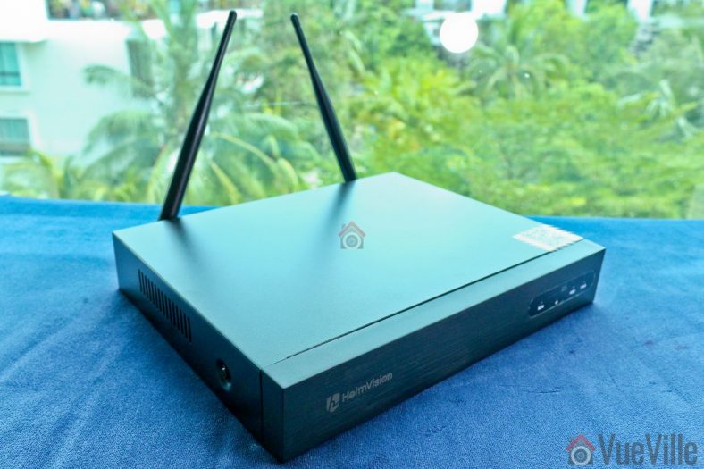
The 8-channel NVR is quite compact and comes pre-installed with two 5dB antenna at the rear. The front face has no buttons, just the Heimvision logo and a set of indicator lamps.
The top of the NVR also has the cloud ID and a QR code that can be scanned by the mobile app for easy setup.
Under normal operation, the three LEDs RUN, HDD and PWR will blink in sequence. Although the NVR seems to support IR controllers, none were included in the box.
The rear of the NVR houses the two antennae, an HDMI port, a VGA port, a USB port (for mouse/keyboard), an RJ-45 Ethernet port, and the 12V/2A power jack.
The underside of the NVR has a sticker showing the model number, FCC ID and other details. Once the hard drive in installed, you will also see the heads of the screws securing it.
Opening up the NVR shows that most of the space inside the NVR is actually unused and left empty for the hard drive. The NVR is powered by the popular Hi3536DV100 H.265/H.264 system-on-a-chip decoder and processor module. This system used an ARM Cortex A7 processor with one SATA hard drive interface.
The NVR firmware identifies the NVR model as the K8204-W.
Heimvision told us that neither this NVR nor the included wireless cameras support ONVIF.
Here’s a list of the various NVR features:
2.4GHz Wi-Fi for camera connections
8 channels supported
Decoding: 4CH 1080P@20FPS or 8CH 720P@20FPS
Real time Playback (Max 8ch)
Mobile push alerts
Email alerts
P2P for remote access
Camera
Four Wi-Fi IP cameras are included with this NVR. The NVR supports 4 more channels, so you could theoretically add more cameras.
You can also buy this camera (model no. CA01) separately from the Heimvision website or [easyazon_link identifier=”B07TD4GK65″ locale=”US” tag=”vueville.com-eaz-20″]Amazon[/easyazon_link], but note that they will work only with specific Heimvision NVRs. They do not officially have ONVIF compatibility.
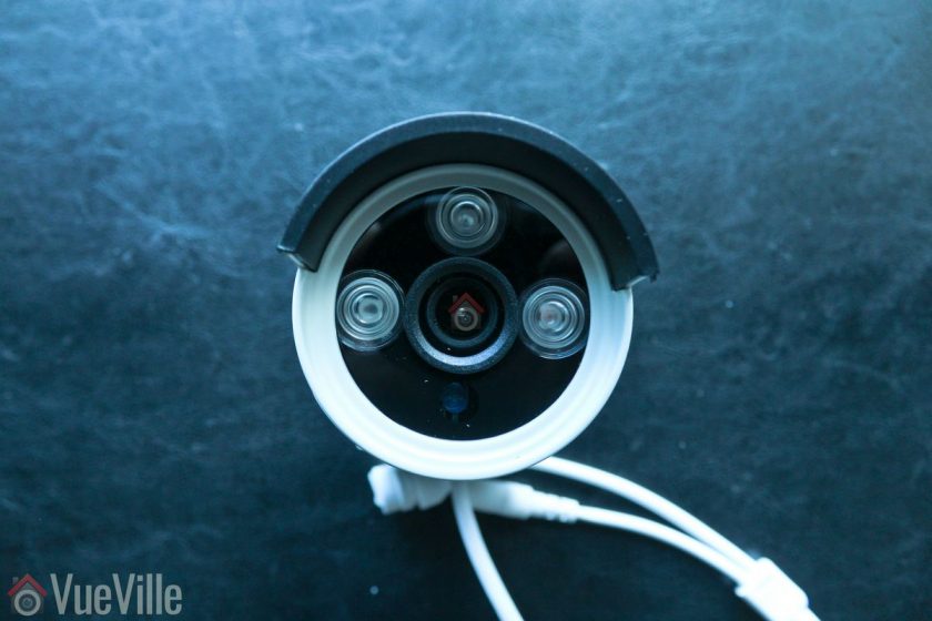
The IP camera has a metal body and is IP66 weather-rated. Each camera comes with a 5dB antenna, a 12V/1A power adaptor, and screws to wall-mount it. The design seems to be inspried by the compact bullet-camera style of the latest Hikvision and Dahua cameras. Overall, the camera has a solid high quality feel to it.
The front of the camera has the 3.6mm fixed lens, and three 850nm EXIR LEDs. I am happy to see that Heimvision chose the more powerful EXIR LEDs instead of the usual ring-type LED arrangement. The daylight sensor is placed just below the lens.
On the features side, the image sensor has a 1080p resolution. The 3.6mm lens has a wide viewing angle of 110°. You won’t find any advanced image processing features like WDR here. Simple motion detection is possible at the NVR end, but not by the camera.
The camera mount is of the 3-axis type, so you can orient the camera in just about any position you want.
While the camera doesn’t support Power-over-Ethernet, it does has an Ethernet port. The camera is wirelessly paired with the NVR at the factory and so is ready to use in Wi-Fi mode. But the Ethernet port allows you to use it as a wired camera if you have an Ethernet point available near the installation site.
I recommend using wired Ethernet as much as possible and to use Wi-Fi only for those parts of your home that are not wired up for Ethernet.
An interesting feature is that the cameras can create something of a mesh network to extend wireless range. Here’s how it works: a camera that is too far away from the NVR can till connect to the NVR through another in-range camera. So the intermediate camera which is in range of the NVR acts like a repeater. This is not automatic though, it has to be set up manually in the GUI.
All in all, the wireless camera feels very solid and like it is built to last. The essential features are there and some innovative features help distinguish it from similar offerings in the market.
Installation & Setup
The included user manual is one of the best I have seen from a Chinese manufacturer.
There are no grammatical errors, the language used is professional and natural, illustrations are clear and the booklet is printed in colour. Other Chinese manufacturers should take note!
Setting up the IP Cameras
Initial setup is super easy because the wireless cameras are paired to the NVR at the factory itself. By default they are set up to create a subnet in the IP range 172.20.14.30-33. I did not see any option to expose the cameras directly to my network beyond the NVR.
Pick an installation location that’s not too far away from the NVR. Don’t install the camera right away though. With wireless cameras, you need to ensure you have a strong connection to the NVR before you permanently install the camera.
Screw the included antenna on to each IP camera.
Plug in the included 12V/1A power adaptor and turn on the power.
Setting up the NVR
If you just plug in the NVR and turn it on, you will see your camera streams on screen in a few minutes. But without installing a hard drive, you won’t be able to record or playback.
So before turning it on, the first thing to do is install a hard drive in the NVR. Heimvision doesn’t provide one, so I used a [easyazon_link identifier=”B008JJLW4M” locale=”US” tag=”vueville.com-eaz-20″]WD RED 3TB[/easyazon_link] drive. I wanted to test the performance of the NVR and didn’t want the drive to be the bottleneck. See my recommendations for NVR hard drives.
The manual has very clear installation steps which is very helpful if you are doing this for the first time. I added my photos below to show you exactly how I did it.
Unscrew the 4 screws from the top and sides of the NVR and slide off the black NVR cover.
The SATA data and power cables are already attached to the main board. Connect these to your hard drive.
Screw the hard drive to the NVR – for this align the hard drive screw holes to the NVR base. Then from the other side, screw the provided screws into each hole one by one.
For continuing the setup I strongly recommend hooking up the NVR using the HDMI or VGA port. Most of the settings are accessible only through the NVR’s built-in GUI.
Connect a mouse to the USB port.
Turn on the NVR with the hard drive installed, it will automatically connect to all the wireless IP cameras and start continuous recording of all channels at 1080p.
Format the hard drive
After a few minutes, you should see the ‘Format successful’ message. Now your cameras are being recorded to the hard drive.
How I connected the NVR to my network
The Heimvision NVR has a built-in virtual network switch and automatically places all the Heimvision wireless cameras in it’s own subnet. How did I know this? Because my Unifi Network Management interface can see the IP addresses of all the wireless cameras: 172.20.14.30 to 172.20.14.33.
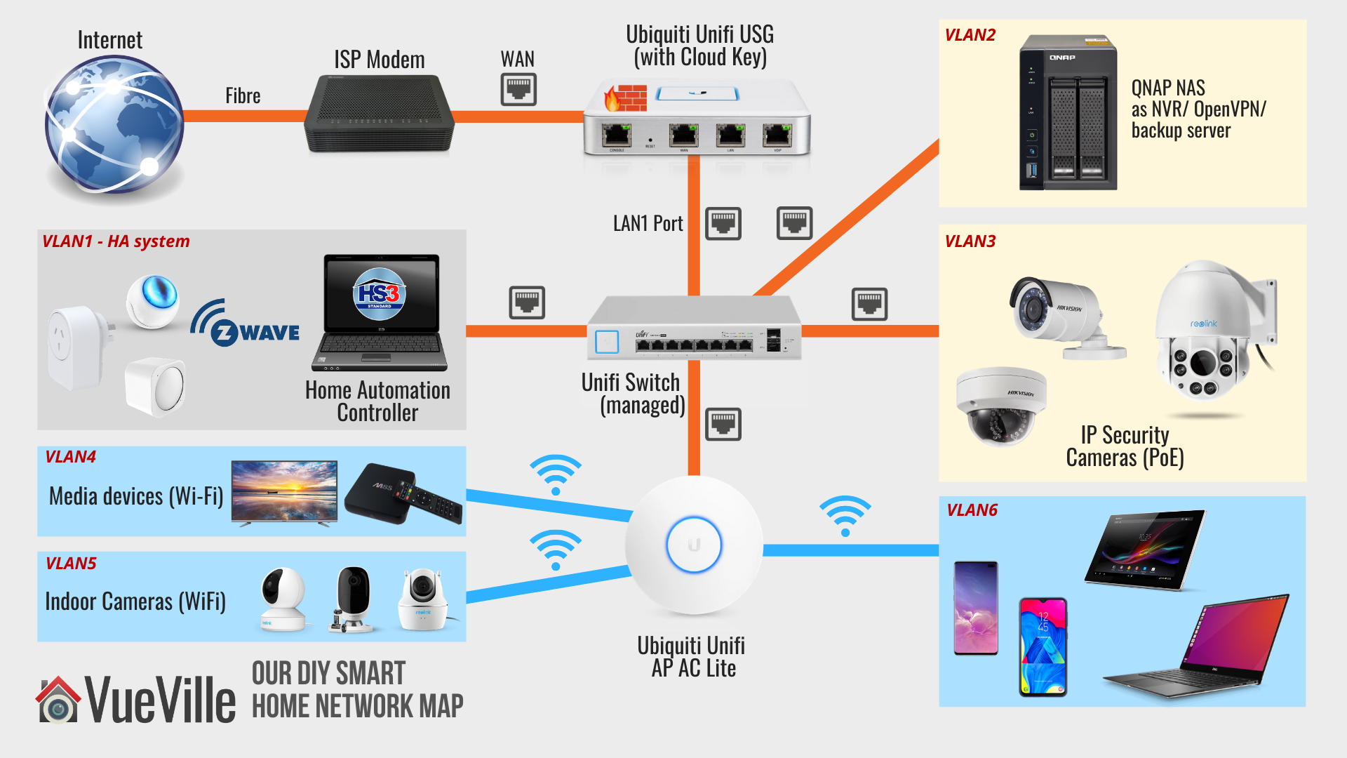
As detailed in my DIY Smart Home Security post, I have wired Gigabit Ethernet throughout my home using Unifi PoE Switches and the Unifi USG firewall. All my existing wired security cameras are already in a VLAN – VLAN number 3 in the network map below.
Our DIY Smart Home Network Map
A quick reminder of my network config: VLAN3 is set up to only accept connections from my LAN, not from the Internet. It is also set up to allow only RTSP streams to go out to the QNAP NAS (VLAN2) and personal devices (VLAN6). I am able to set up such precise rules because I use the Unifi US-8-60W managed switch and the Unifi USG firewall.
So I added the NVR to VLAN3 using Ethernet. Now comes the fun part – accessing the NVR from the rest of my network.
The only thing I wanted to pull from the Heimvision NVR are the RTSP video streams. But the NVR currently doesn’t support RTSP streams – Heimvision tells me this is coming soon. So my alternative for now is to use the EseeCloud PC software. This software requires a specific port to be open on the NVR to connect to it.
By inspecting the packets between my laptop (VLAN6) and the NVR, I saw that EseeCloud uses port 10000 of the NVR. So I created an additional USG rule to allow outgoing (established) connections from the NVR only on port 10000, to VLAN6. Boom! EseeCloud was up and running securely.
Strictly for the purposes of this review, I also allowed port 80 on the NVR to use the browser admin page of the NVR and for the HeimKits mobile app to work.
For the cloud P2P option to work, I tested the NVR in a totally separate VLAN with full access to the Internet. This was the easiest way to allow P2P cloud connections between the NVR and Heimvision servers.
Live viewing the cameras
There are a few different ways of interacting with the NVR and video streams:
Connect the NVR to a TV or monitor
Use the PC NVR software
Use the mobile app
Access the built-in management web page of the NVR
The user manual details each of the methods and how to set them up.
Live viewing the cameras using HDMI/VGA
HDMI is the easiest way to hook up the NVR to your TV. The NVR’s built-in interface is the most polished option and has the most features.
You can configure the cameras, live-view them, set up motion detection and play back recorded footage.
Live viewing the cameras using the EseeCloud PC Software
Here are the steps I used to set it up.
As per the manual, I downloaded and installed the EseeCloud software.
On opening the software, I logged in with the default username (admin) and password (blank).
Click Add at the top right
I entered the IP address, and changed the number of channels to 4, all others were left at default
You will see a message at the bottom right – “Added the device successfully”
Also you should see your NVR listed at the top right. Click on each channel to activate it.
Clicking the ‘Device Management’ option will prompt Windows to allow the software through the firewall.
Clicking on ‘Playback’ will open the video review section
Reviewing recorded footage
There are three ways to view the recorded footage – on a TV/monitor through HDMI/VGA, the PC NVR software, and mobile app.
I recommend the HDMI/VGA method because of two major reasons:
This is the only way to fast forward (scrub) through footage quickly, at upto 32x speeds.
Simultaneous playback of all 4 channels works well only in this method.
You can select individual video files and back it up to a USB drive.
Whichever method you choose, the timeline shows 24/7 recording (red), motion detection triggers (green) and alarm triggered recording (blue). This is extremely useful when you are looking for motion detection events to review.
The PC software method (EseeCloud) is great for directly exporting videos and screenshots directly to your PC hard drive. But otherwise it doesn’t offer you any advantage over the HDMI/VGA method.
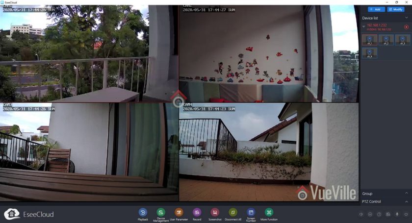
EseeCloud PC Software
You can start each channel’s playback manually and switch each channel’s main stream and sub stream by clicking the SD/HD button.
Synchronous playback is possible by checking the button highlighted in the screenshot above.
However playing more than 2 channels’ main streams (1080p) simultaneously slows down the playback of all the channels. The NVR is powerful enough to handle this while connected through HDMI/VGA. So I conclude that this is just the EseeCloud software not being up to scratch. I had to use the sub stream (SD option) on all channels if I wanted simultaneous playback.
Another limitation is that you cannot increase the playback speed, in other words you cannot fast forward. This is a basic feature and it is disappointing to see it missing in this rather good-looking software.
Performance
Video Quality
1080p is the bare minimum I recommend for home CCTV surveillance. The cameras produced sharp, crisp video during the daytime.
At night, noise was well controlled and detail was high. The powerful EXIR LEDs helped illuminate the scene evenly and I was glad to not see the dreaded flashlight effect that the conventional ring-type LEDs produce.
There are no settings to control the brightness of the LEDs and there are no advanced features to dynamically control the infrared light output.
Motion detection
The Heimvision HM241 is able to do both pre-recording and post-recording. This means the NVR is able to record not just what happens after motion was detected but a few seconds before the trigger as well. This is a great feature and something that I always look for in a security camera system.
The post-record feature lets you decide how many seconds the camera should record after the last motion trigger. The default is 15 seconds.
Wireless performance
Being a wireless surveillance system, the cameras are limited to 1080p resolution. While 3MP or 4MP are great, 2.4GHz Wi-Fi is simply not fast enough to reliably carry that bandwidth over large distances.
You could ask why not use 5GHz? Well the useful range of 5GHz Wi-Fi is very low and frankly useless for video surveillance. If you have solid concrete walls, 5GHz Wi-Fi again becomes pretty useless over any reasonable distance.
I placed the Wi-Fi cameras at varying distances from the NVR, with varying number of internal and external walls in between them.
My objective was to stress test the cameras and see how far away I could place the cameras and still enjoy a stable wireless connection.
Cam1: 30 feet, one external concrete wall, two solid brick walls
Cam2: 10 feet and 1 solid brick wall
Cam3: 20 feet and 2 solid brick walls
Cam4: 10 feet, 1 floor above the NVR, through a solid concrete floor and one external concrete wall
All the cameras were able to push full 1080p video at the default VBR setting. Even though CAM1 was at the limit of the camera’s Wi-Fi range, the NVR was able to maintain the full 2 Mbps bitrate. The ability of the signal to penetrate multiple solid brick and concrete walls is very impressive.
I would imagine the wireless range can easily go to 50+ feet in a timber frame house, given the strong performance in my house which has very thick concrete and brick walls.
Mobile App
For testing the mobile app as most users would, I allowed the NVR full access to the Internet. This is also required for the P2P cloud features of the camera to work. A free HeimVision P2P cloud server account is required to receive real-time push notifications as well.
You can use the app as anonymous user without creating an HeimVision cloud account, but then you won’t get push notifications.
Live view and Playback
So what should you be looking for when it comes to push notifications? The speed and reliability of the push notifications reaching you. You want the NVR to send you push notifications immediately after it detects motion.
I installed the ‘HeimKits’ mobile app as per the instruction manual and took it for a whirl.
Download and install the app from your mobile phone’s app store.
Tap the + button to add your NVR
Select Kit and an automatic scan will start. This will find the kit and set t up for most people. In my case since I had put the NVR in a different subnet from my main LAN, the scan failed.
I tapped the ‘Add Manually’ button and again tapped the other ways to add button to get the local setup option. If you want to set up the NVR so that you can access it remotely and are hapy to use HeimVision’s P2P servers, use the cloud setup option. This is also the default.
I entered all the details and tapped complete.
I was then taken to the live view page. Success!
The mobile app did ask for all sorts of permissions on Android, but the only one needed for the app to function is ‘Storage’. I denied access to the Camera, Microphone and everything else. Call me paranoid but that’s how we roll at VueVille!
The interface is very modern and had a very polished look and feel. This felt like a properly thought-through app with a good design language and flow.
You can live view cameras in groups of 1, 4, 6 or 8. Landscape mode is supported. You can also switch between the SD and HD streams. It is also possible to take a screenshot or a video clip of any channel straight to your mobile phone.
On the playback screen, the view is limited to one camera at a time. No simultaneous playback here! But the timeline is super responsive and motion detection events are marked clearly on the timeline. One gripe is that I could not directly download the motion detection video clip I was viewing to my phone. However there is a (well-hidden) export feature on the top left menu where you can specify a channel and a time range to search. This will bring up all the clips and then you can download the one that contains the time period of interest.
Push Notifications
To get push notifications to the HeimKits mobile app, you need to do a few things:
Access the NVR settings using an HDMI/VGA cable and a TV:
Enable motion detection for each channel
Define the arming time schedule for each channel
Turn on ‘App alarms’ for each channel
Create a Heimvision cloud account and login with that to add your NVR. Anonymous mode is not enough.
Enable push notifications in the mobile app settings
Once you have done all that, you are ready to go! In my testing, I got push notifications in the HeimKits app instantaneously. The success rate of receiving the push notifications over multiple motion triggers was also very good.
Touching the notification takes you to a list of all the alerts received in descending order of time. Touch the alert you want and then you are taken to a quick preview of the alert clip. If you want to see what happened just before the motion was detected, tap ‘Full Video’. Yes, the NVR supports pre-recording, not just post-recording. So you won’t miss the crucial few seconds before motion is detected.
Security & Privacy
For using push notifications, you need to activate the free HeimVision cloud P2P service. This does provide fuss-free remote access for live view, playback and live streaming.
The two things we didn’t like are:
You cant get even local network push notifications without activating the cloud feature
The cloud features requires you to create an account (free of charge)
If you are concerned about using the Cloud P2P service for privacy reasons, it is not enough to simply disable the cloud service. You have to place the NVR behind a firewall and configure firewall rules properly so that only connections you want are allowed.
The HeimVision HM241 is a high quality starter NVR kit with strong wireless performance and a good feature-set for a great price. Setup is easy and fuss-free, and takes just minutes thanks to the wireless cameras being pre-configured with the NVR. We would still like to see a variant with an included hard drive to make the setup fully plug-and-play.
Video quality is great at 1080p FullHD, and the powerful IR LEDs provide good illumination at night. The mobile app is a joy to use; you can live-view, receive instantaneous push notifications and review footage with ease from anywhere in the world using the free cloud P2P service.
If you decide to go wired in the future, the system can grow with you – the wireless cameras have Ethernet ports as well.
For the price point it targets, its fine to not have advanced motion detection or redundant storage. However we were not pleased to see that push notifications don’t work unless the cloud P2P service is used. This rules out receiving push notifications locally in your home network or via a VPN connection.
Video quality is great at 1080p FullHD, and the powerful IR LEDs provide good illumination at night. The mobile app is really good; you can live-view, receive instantaneous push notifications and review footage with ease.
In conclusion, the HeimVision HM241 is a very affordable wireless home surveillance kit and is fantastic value for money.
[review]
Where to buy
[easyazon_link identifier=”B07RKJDK65″ locale=”US” tag=”vueville.com-eaz-20″]Check Price on your local Amazon site[/easyazon_link]
Alternatives
The nearest competitor is the [easyazon_link identifier=”B07VWHXF4C” locale=”US” tag=”vueville.com-eaz-20″]Reolink RLK4-211WB4-S[/easyazon_link] which has a similar price point and very similar features.
The next step up would be the Amcrest [easyazon_link identifier=”B0785GZ88X” locale=”US” tag=”vueville.com-eaz-20″]NV2104-IP2M-852W4[/easyazon_link] which is significantly more expensive but supports ONVIF and has a 4K NVR.
One of the most common questions I have been getting about our DIY Home Security system is this: How to setup a VLAN and firewall rules to block IP cameras from accessing the Internet?
Wondering why you would want to do that? Here are a few good reasons:
Most security cameras like to phone home to their manufacturer’s servers. There’s no need to, it’s not good for your privacy or your network’s security.
Most security cameras have poor security and can be easily hacked, and none of us want someone spying on our indoor security cameras!
Moreover, security cameras are at risk of being hacked to join botnets, which then attack other devices on your network or the Internet.
For the longest time, I was put off by my perception that firewalls and VLANs are too complex for me. Looking at most networking gear, I would be right.
The beauty of the Ubiquiti Unifi system I now use is that you don’t need to be a networking wizard to secure your security cameras and your home network. Using the excellent Unifi Controller GUI, I was able to block my security cameras from the Internet without getting a university degree in networking.
So in this tutorial, I am going to show you how to:
Create a Virtual LAN (VLAN) for your wireless security cameras
Create a dedicated Wi-Fi network for your wireless security cameras and assign this network to the VLAN
Create 3 firewall rules to prevent the cameras accessing the Internet (but allow other devices on your network to access them locally or just for pulling the RTSP video streams)
NOTE 2: This tutorial is for those who only access their IP cameras via the local IP (such as 192.168.X.X). So for remote access, you would VPN into your home network and then access your cameras using their local IP address. If you require your cameras to be exposed to the Internet using P2P or DDNS, this tutorial is not for you! Most camera apps that have a plug ‘n play setup option use remote P2P servers! Blocking internet access to these cameras will cause them to fail.
Okay, so if you are accessing your IP cameras through the local IP address (from home or remotely via a VPN such as OpenVPN), let’s continue!
What you will need
You will need the [easyazon_link identifier=”B086967C9X” locale=”US” tag=”vueville.com-eaz-20″]Unifi UDM Pro[/easyazon_link] which is a very versatile networking device along with at least one other Unifi Wi-Fi Access Point (WAP) such as the [easyazon_link identifier=”B08QG92M83″ locale=”US” tag=”vueville.com-eaz-20″]Unifi AP 6 Lite[/easyazon_link].
Preparation: Planning your home network
To make sense of this topic, we need a basic understanding of how network connections and firewalls work. I am assuming your security camera has an RTSP video stream and that’s what we are trying to view.
The relevant networking terminology is:
WAN (Wide Area Network) refers to the Internet.
LAN is your local home network.
For simplicity, let’s assume your mobile phone is connected to your general Unifi Wi-Fi network. In the Unifi world, your phone is therefore in the LAN group. By default, devices in the LAN group can access any part of the local network and the Internet.
When you use your mobile phone IP camera app (like tinyCAM Monitor Pro) to view the stream of your wireless IP camera, the phone sends an RTSP connection request to your IP camera. The camera accepts it and sends the stream back out to your phone.
Now, the idea here is to segment your home network into different groups, based on what type of access control you want to impose on those devices. In networking parlance, you would create a Virtual LAN or VLAN to group these devices together.
When you create a VLAN in the Unifi Controller software and assign a device to it, the router will tag each data packet of that device with a VLAN ID.
How do VLANs work in practice? How do I assign a device to a VLAN?
For wired devices, you can assign each port of a managed switch to a specific VLAN. Then all devices connected to that network will be in the same VLAN. That’s what happens with a Unifi Switch. So if you connect your wired PoE IP cameras to a port that’s assigned to VLAN 25, all those IP cameras are now in VLAN 25.
For wireless devices, you create separate Wi-Fi networks for different groups of devices and then assign a VLAN ID to each Wi-Fi SSID you create. So you would create a Wi-Fi network called ‘IP Cameras’, assign that Wi-FI SSID to VLAN 35, and connect all your wireless cameras to that network. All those wireless cameras are now in VLAN 35.
Then you can create firewall rules for each VLAN to control data flow in very granular detail (if you choose to!).
In summary, segmenting your home network into different VLANs allows you to precisely control how and where data is allowed to go.
For example, you may want your media boxes to reach the Internet to access Netflix, Amazon Prime, Hulu etc. But you may not want them to access the rest of your network. Why? Because your cable provider’s cheap no-name box probably has weak security and may be the easiest way for hackers to get inside your home network. So that’s one VLAN for your media boxes.
If you are using wired PoE cameras outside your home, anybody can access your entire home network through that network cable! So you should put wired cameras also into their own VLAN and isolate it from the rest of your network.
Its also a very good idea to make all your security cameras fully local by blocking them from the Internet. Many of them phone home regularly and are also easy targets for botnets and the like.
I have created separate VLANs for my PoE cameras and Wi-Fi cameras. I also have separate VLANs for my home automation system and the default VLAN Unifi created for the guest Wi-Fi network. Please note that I have an older Unifi setup that involves a USG and switch combo, which you can simply replace with a single [easyazon_link identifier=”B086967C9X” locale=”US” tag=”vueville.com-eaz-20″]Unifi UDM Pro[/easyazon_link] device!
Our DIY Smart Home Network Map in 2022
What’s in scope of this tutorial
To keep this tutorial easy to follow and understand, I am not going to show how to replicate my entire network setup. That would be a 10,000 word post at least and this tutorial is already long enough as it is!
You will learn the core ideas here and then you can create more VLANs and more firewall rules to suit your specific needs. Just ask me in the comments section if you have any questions.
If you want your camera to send ONVIF motion detection notifications to your NVR, you need to create additional firewall rules to allow outgoing connections from the camera’s ONVIF port (usually port 80, some Reolink cameras use port 8000). Consult your IP camera manual to see which ports are used for these features.
Step 1. Create a VLAN for your security cameras
For simplicity, I will take the example of creating a VLAN and Wi-Fi SSID for wireless cameras.
In the Unifi world, a VLAN is the same as a ‘network’. So you have to create a ‘network’ with a VLAN ID of your choice.
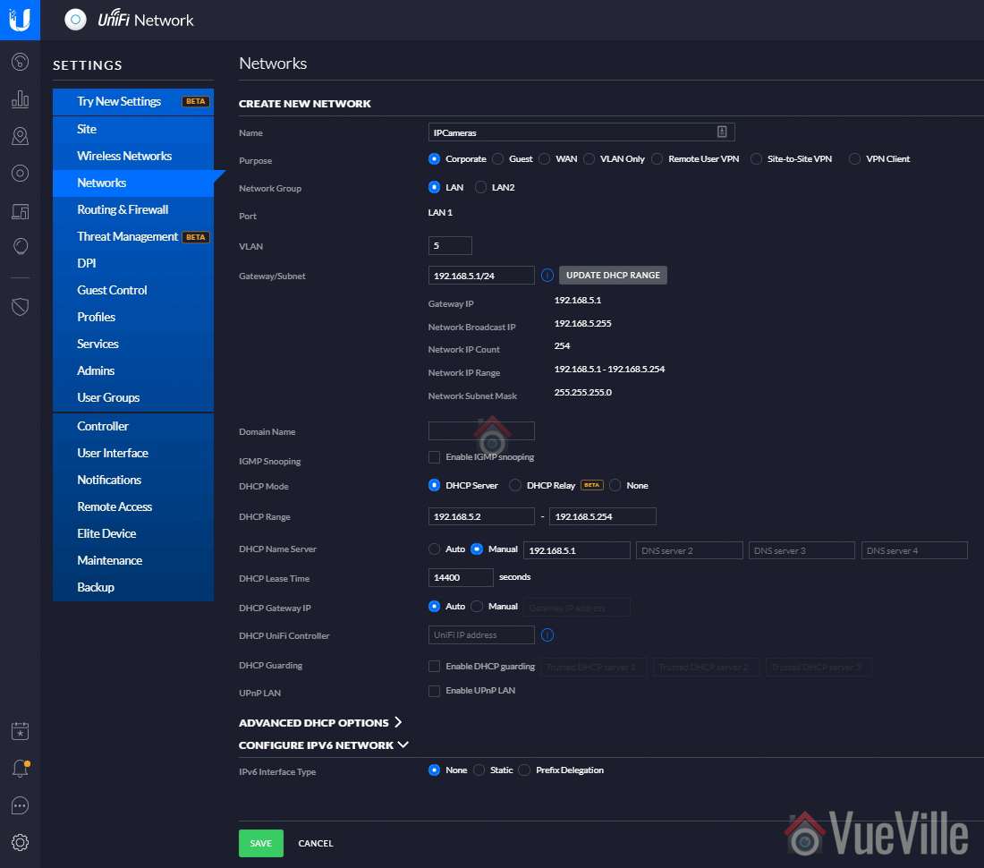
Log into your Unifi controller and navigate to Settings > Networks. I am using the classic settings view.
Click on ‘ + Create New Network’
Enter a name, I chose ‘IPCameras’
Leave all the settings at defaults except the following
VLAN: Select a number, I used 5 as per my home network plan. For convenience, it’s a good idea to keep the VLAN ID same as the subnet you choose in the next step.
Gateway/Subnet: My main network is 192.168.1.X, so I chose a subnet of 192.168.5.X for this VLAN. So enter your desired subnet followed by ‘/24’. So I entered: 192.168.5.1/24
DHCP Range: 192.168.5.2 – 192.168.5.254 (replace 5 with your selected subnet number)
DHCP Name Server: Choose manual and enter 192.168.5.1 (replace 5 with your selected subnet number)
DHCP lease time: 14400 sec
Hit Save
Step 2. Create a dedicated Wi-Fi network for your security cameras
Next let’s create a Wi-Fi SSID for your wireless cameras to connect to, and assign this SSID to the ‘network’ created earlier.
Navigate to Settings > Wireless Networks. I am using the classic settings view.
Click ‘+ Create New Wireless Network’
Under the ‘Create New Wireless Network’ section
Enter the SSID name you want, I chose ‘WirelessIPCameras’
Choose WPA Personal security and enter a security key (password for this Wi-Fi network)
Don’t apply guest policies
Expand the ‘Advanced Options’ section to reveal it
Select VLAN and enter the VLAN ID you have chosen. I entered 5.
Hide SSID – select this for better privacy
If you have created a user group, you can assign one here. Useful for bandwidth rate limiting etc but not relevant in our case.
Combine Name/SSID: Select this. If your camera supports the 5 GHz band, it will be used instead of the slower 2GHz band. Most security cameras do not.
Leave all other settings at default
Hit Save
Wait a few minutes for the Unifi controller to provision the new wireless network.
Step 3: Create 3 Firewall rules to block camera access to the Internet
We will create 3 firewall rules for our security camera VLAN and those rules will apply to all the cameras in this VLAN.
The logic behind our firewall rules
We will be editing the WAN OUT (connections going out to the Internet), and LAN OUT (connections going from inside a VLAN to the rest of your local network or Internet). We will use the default rules for LAN IN (connections coming into a VLAN from the rest of your local network or the Internet):
We do not want our cameras to accept connections from the Internet. We want to allow only connections from the local network. You can achieve both of this through a single firewall rule, but we don’t need to create it manually. The Unifi USG firewall by default ‘drops’ or ignores all unsolicited incoming connections from the Internet. Any good firewall will do this by default. You can find this default rule under then WAN IN section of the firewall rules.
We also do not want the cameras to initiate connections to the Internet (WAN). In other words, we do not want them to ‘phone home’ to the manufacturer’s servers. So we will define a WAN OUT rule blocking all outgoing connections initiated by this VLAN. That’s Rule 1.
To further tighten up things, even when a connection request is received by this VLAN from anywhere else in the local network, I want the firewall to allow the cameras only outgoing RTSP connections. That’s another LAN OUT rule and rule no.2 for today.
We also don’t want the cameras to initiate any other connection to the rest of the local network (LAN). So we will define a LAN OUT rule blocking all outgoing connections initiated by this VLAN. That’s Rule 3.
Whom this tutorial/approach is not for
Do you want to use your camera manufacturer’s P2P-based mobile app (Dahua P2P, Reolink P2P etc.)? Then this tutorial will not help you – blocking Internet access for the cameras will kill the P2P feature also.
This tutorial is only for those who only want to use the RTSP video stream of their cameras (use all 3 rules below) OR want to use a mobile app set up using a local IP address (use only rule 1 below).
Creating the rules
Right, let’s do it.
Navigate to Settings > Routing & Firewall. I am using the classic settings view.
Select the Firewall tab and then Rules IPv4
Rule 1 – Block access to the Internet (WAN)
Select the WAN OUT tab, and click ‘+ Create New Rule’
Name this rule ‘Block IPCameras going out’
Under Advanced, enable logging and select all the states
Under Source, select Network and pick the VLAN network you created earlier (IPCameras in the step 1 above). Ensure IPv4 subnet is selected in the dropdown next to it.
Leave everything else at defaults
Hit Save
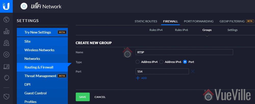
Create a port group for rule 2
Navigate to Firewall > Groups
Click on ‘+Create New Group’
Name it ‘RTSP’ and enter port as 554 (or whichever port your camera uses for RTSP)
Hit Save
Rule 2 – Allow only RTSP outgoing connections in response to incoming requests from the LAN
Select the LAN OUT tab, and click ‘+ Create New Rule’
Name this rule ‘Allow only RTSP port 554 out established’
Select state ‘Established’
Select Source type ‘Address/Port Group’
Under port group, select the RTSP port group you created earlier
Leave everything else at defaults
Hit Save
Rule 3 – Block access to the rest of your home network (LAN)
Select the LAN OUT tab, and click ‘+ Create New Rule’
Name this rule ‘Drop all outgoing’
Under Advanced, select all the states
Under Source, select Network and pick the VLAN network you created earlier (IPCameras in the step 1 above). Ensure IPv4 subnet is selected in the dropdown next to it.
Leave everything else at defaults
Hit Save
The order of these rules is very important – after creating the rules above, make sure that under the ‘LAN OUT’ section rule 2 is on the top of the list and rule 3 should be after it. Because that’s the order in which the firewall will process the rules.
Now let’s test the rules to see whether they are working as intended. Temporarily connect a laptop or mobile phone to the Wi-Fi SSID you created. You should not be able to reach the Internet or access any other local network resource such as the Unifi controller dashboard. If all is well, disconnect from the Wi-Fi network.
Now simply connect your wireless cameras to the Wi-Fi SSID. Re-connect your mobile phone or laptop to your regular Wi-Fi network. Now try to access the RTSP stream of your cameras – you should get a video stream.
Congratulations! You have now secured your security cameras and your network is a whole lot safer.
Ever wondered what’s in the air you are breathing? All over the world, our cities are getting more and more polluted. Air pollution is an invisible killer that takes over 4 million lives every year.
But it’s not just outdoor air that can be harmful. Common activities like cooking or burning candles togetherwith poor ventilation can cause a severe drop in indoor air quality. This is because burning of fuels release countless numbers of tiny particles into the air.
In the past, air quality sensors were expensive and not very accessible. But now with readily available micro-controllers like the Arduino and affordable DIY sensors, we can make our own DIY Arduino air quality sensor in less than 15 minutes.
A quick note: As an Amazon Associate I earn from qualifying purchases. This post contains affiliate link(s). An affiliate link means I may earn advertising or referral fees if you make a purchase through my link, at no extra cost to you.
Air Quality Monitoring
The specific methods used to measure air quality depends on whether you are thinking of measuring indoor or outdoor air quality.
Indoor air quality is affected by pollutants such as dust, CO2 and Volatile Organic Compounds (VOC). By measuring one or more of these, we can get a good idea of indoor air quality. Different sensors are required for each of these pollutants.
Outdoor air quality usually depends on pollutants from combustion engines. The burning of fuel produces tiny particles called Particulate Matter (PM) that are classified by how small they are.
The smaller the particles, the more dangerous they are. PM2.5 refers to atmospheric particulate matter (PM) that have a diameter of less than 2.5 micrometres. This is about 3% the diameter of a human hair.
Exposure to PM2.5 particles over a long period of time is harmful for health. The key to managing your exposure to these harmful particles is to be able to measure it.
For this tutorial, we will focus on measuring PM2.5 and its close cousins, PM1.0 and PM10 (particle size of 1 and 10 micrometres respectively).
These figures will give us the Air Quality Index (AQI), the most commonly used metric for measuring and comparing air quality levels of different cities in the world.
You will be able to use this Arduino Air Quality Monitor indoors to measure pollution from cooking, smoking etc., and outdoors to measure the air quality of your neighbourhood.
Air Quality Sensors
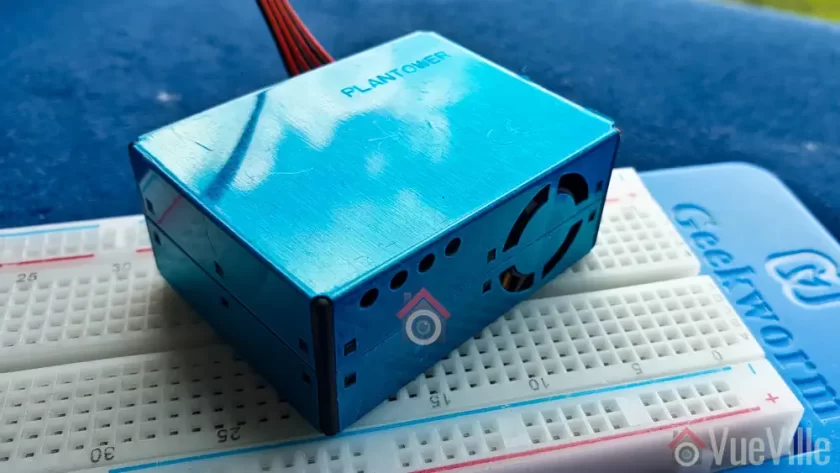
The most common type of air quality sensor that measures PM2.5 uses a laser to detect particulate matter. There are two types of these laser-based sensors: ones without a fan like the Samyoung DSM501A and ones which have a fan like the Plantower PMS5003.
The fanless versions are cheaper but are also less accurate. The Plantower PMS5003 that we will use is the best DIY model that is still quite affordable.
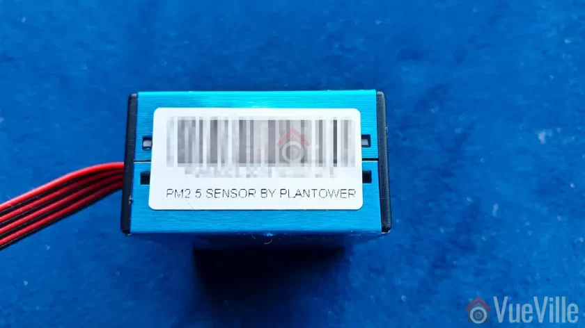
PMS5003 Air Quality Sensor
The Plantower PMS5003 sensor can detect particles as small as 0.3 micrometres. This is why the model number of the sensor ends with ‘003’. The 5 refers to the series generation.
You can see the air intake fan on the back. That’s what makes this sensor more accurate than fanless designs like the Samyoung DSM501A.
Actually the PMS5003 is not a current generation model, that’s actually the PMS7003. If you can find the PMS3003 or PMS7003 at a better price than the PMS5003, by all means go for it. The Arduino code may be a bit different though.
Working principle
The PMS5003 uses a laser to scatter and radiate suspended particles in the air. It then analyses the scattered light to obtain the curve of how the light scattering changes with time.
The sensor then calculates the number of particles of various diameters per unit 0.1L volume of air.
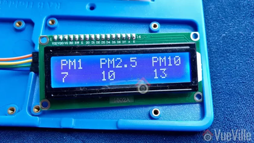
The PMS5003 can output the following:
PM1.0, PM2.5 and PM10.0 concentration in both standard & environmental units
Particulate matter per 0.1L air, categorized by 0.3um, 0.5um, 1.0um, 2.5um, 5.0um and 10um sizes
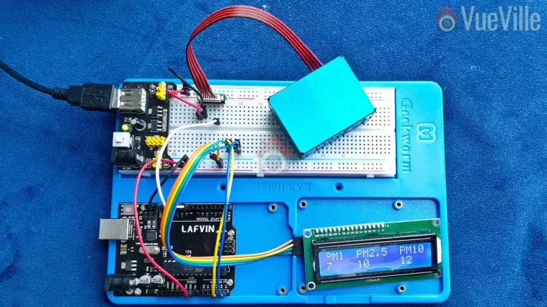
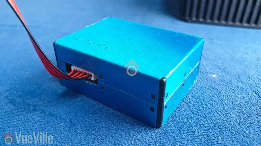
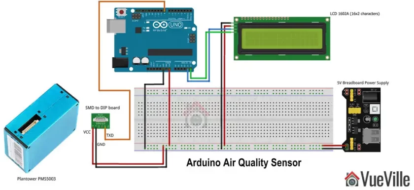
Connecting the PMS5003 to Arduino
The PMS5003 has an 8-pin JST port and comes with a cable that fits the port. But the easiest way to connect the sensor to the Arduino is by getting a JST to DIP 2.54mm standard spacing adaptor board.
This makes it super easy to interface the sensor to your Arduino.
Components required
If you have an [easyazon_link identifier=”B01D8KOZF4″ locale=”US” tag=”vueville.com-eaz-20″]Arduino Starter Kit like this one[/easyazon_link], the only thing you need is the PM2.5 sensor.
Here’s the full parts list.
[easyazon_link identifier=”B008GRTSV6″ locale=”US” tag=”vueville.com-eaz-20″]Arduino Uno Rev3[/easyazon_link]
[easyazon_link identifier=”B0787H244V” locale=”US” tag=”vueville.com-eaz-20″]Plantower PMS5003 Air Quality Sensor[/easyazon_link]
[easyazon_link identifier=”B077SFGWYP” locale=”US” tag=”vueville.com-eaz-20″]Breadboard power supply[/easyazon_link]
Connecting Wires
Wiring diagram
Click to enlarge
PMS5003 sensor
Connect the PMS5003 as below if you are using a JST to DIP 2.54mm standard spacing adaptor board (recommended):
VCC to 5V (do not use Arduino to supply this voltage)
GND to common ground with Arduino
Arduino pin #8 to TX pin on sensor (this is incoming data from the sensor)
Leave pin #9 disconnected even though it is defined in the code below
1602A LCD display
I strongly recommend using the I2C method to connect the 1602A LCD display to your Arduino. This means you need to use just 4 pins instead of over 9 with the traditional method.
For this get a version of the LCD that is already soldered with an I2C module. Most of the starter kits include this version so that beginners don’t get overwhelmed.
This is how you wire it:
VCC to 5V (do not use Arduino to supply this voltage)
GND to common ground with Arduino
SDA to pin A4
SCL to pin A5
Arduino Code
Copy the code below into a new .ino file, compile it and upload to your Arduino. That’s it!
Leave a comment below if this article helped you!
// Created by VueVille.com based on the Adafruit code for PMS5003 PM2.5 sensor// Read the full how-to article at https://www.vueville.com/arduino/arduino-air-quality-sensor/// Connect the PMS5003 like this if you are using a JST to DIP 2.54mm standard spacing adaptor board (easier):// VCC to 5V (do not use Arduino to supply this voltage), GND to common ground with Arduino// Arduino pin #8 to TX pin on sensor (this is incoming data from the sensor), leave pin #9 disconnected even though it is defined in the code below// Connect the 1602A LCD like this if you are using an I2C module (easier)// VCC to 5V (do not use Arduino to supply this voltage), GND to common ground with Arduino// SDA to pin A4// SCL to pin A5#include<SoftwareSerial.h>SoftwareSerialpmsSerial(8,9);#include<Wire.h>#include<LiquidCrystal_I2C.h>//I2C pins declaration for 1602A with I2C moduleLiquidCrystal_I2Clcd(0x27,2,1,0,4,5,6,7,3,POSITIVE);unsignedlongpreviousMillis=0;unsignedlonginterval=1000;//Refreshes the LCD once every 1000ms (1 second) without holding up the Arduino processor like delay() does. If you use a delay(), the PMS5003 will produce checksum errorsvoidsetup(){// debugging output, don't forget to set serial monitor to 115200 baudSerial.begin(115200);// sensor baud rate is 9600pmsSerial.begin(9600);lcd.begin(16,2);//Defining 16 columns and 2 rows of lcd displaylcd.backlight();//To Power ON the back light}structpms5003data{uint16_tframelen;uint16_tpm10_standard,pm25_standard,pm100_standard;uint16_tpm10_env,pm25_env,pm100_env;uint16_tparticles_03um,particles_05um,particles_10um,particles_25um,particles_50um,particles_100um;uint16_tunused;uint16_tchecksum;};structpms5003datadata;voidloop(){// Serial output code beginsif(readPMSdata(&pmsSerial)){// reading data was successful!Serial.println();Serial.println("---------------------------------------");Serial.println("Concentration Units (standard)");Serial.print("PM 1.0: ");Serial.print(data.pm10_standard);Serial.print("\t\tPM 2.5: ");Serial.print(data.pm25_standard);Serial.print("\t\tPM 10: ");Serial.println(data.pm100_standard);Serial.println("---------------------------------------");Serial.println("Concentration Units (environmental)");Serial.print("PM 1.0: ");Serial.print(data.pm10_env);Serial.print("\t\tPM 2.5: ");Serial.print(data.pm25_env);Serial.print("\t\tPM 10: ");Serial.println(data.pm100_env);Serial.println("---------------------------------------");Serial.print("Particles > 0.3um / 0.1L air:");Serial.println(data.particles_03um);Serial.print("Particles > 0.5um / 0.1L air:");Serial.println(data.particles_05um);Serial.print("Particles > 1.0um / 0.1L air:");Serial.println(data.particles_10um);Serial.print("Particles > 2.5um / 0.1L air:");Serial.println(data.particles_25um);Serial.print("Particles > 5.0um / 0.1L air:");Serial.println(data.particles_50um);Serial.print("Particles > 10.0 um / 0.1L air:");Serial.println(data.particles_100um);Serial.println("---------------------------------------");}// Converting the sensor readings to string values that the LCD can displayStringpm1String=String(data.pm10_standard);Stringpm25String=String(data.pm25_standard);Stringpm100String=String(data.pm100_standard);// Non-blocking code for displaying the sensor readings on the LCDunsignedlongcurrentMillis=millis();if(currentMillis-previousMillis>interval){previousMillis=currentMillis;lcd.clear();//Clear the screenlcd.setCursor(0,0);lcd.print("PM1 PM2.5 PM10");lcd.setCursor(0,1);lcd.print(pm1String);lcd.setCursor(5,1);lcd.print(pm25String);lcd.setCursor(12,1);lcd.print(pm100String);}}// Code for calculating the sensor readings booleanreadPMSdata(Stream*s){if(!s->available()){returnfalse;}// Read a byte at a time until we get to the special '0x42' start-byteif(s->peek()!=0x42){s->read();returnfalse;}// Now read all 32 bytesif(s->available()<32){returnfalse;}uint8_tbuffer[32];uint16_tsum=0;s->readBytes(buffer,32);// get checksum readyfor(uint8_ti=0;i<30;i++){sum+=buffer[i];}/* debugging for (uint8_t i=2; i<32; i++) { Serial.print("0x"); Serial.print(buffer[i], HEX); Serial.print(", "); } Serial.println(); */// The data comes in endian'd, this solves it so it works on all platformsuint16_tbuffer_u16[15];for(uint8_ti=0;i<15;i++){buffer_u16[i]=buffer[2+i*2+1];buffer_u16[i]+=(buffer[2+i*2]<<8);}// put it into a nice struct :)memcpy((void*)&data,(void*)buffer_u16,30);if(sum!=data.checksum){Serial.println("Checksum failure");returnfalse;}// success!returntrue;}


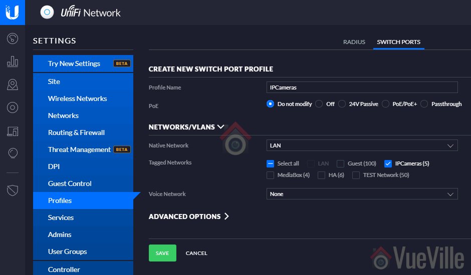


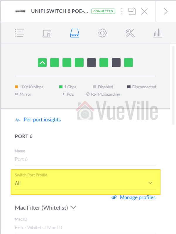
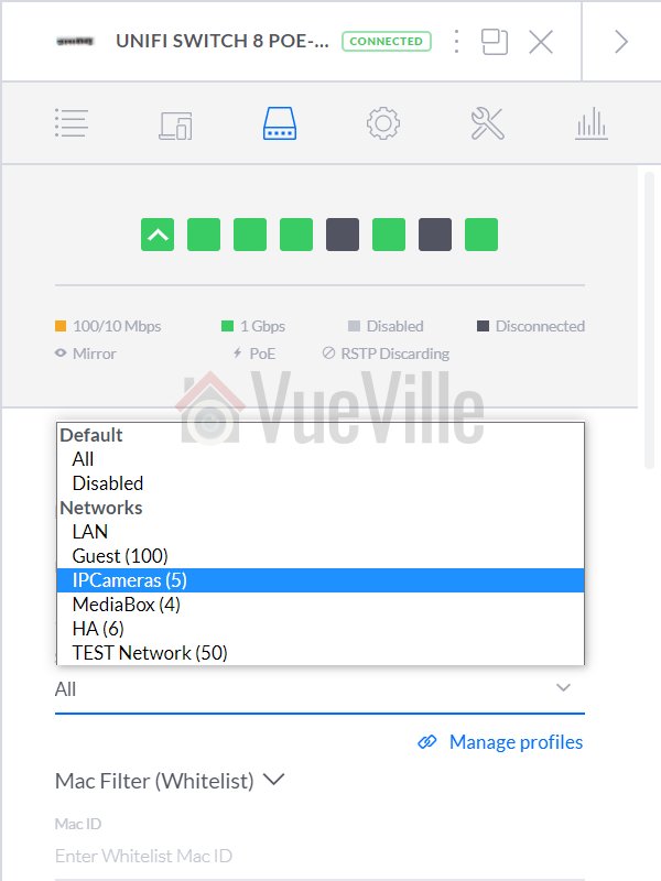


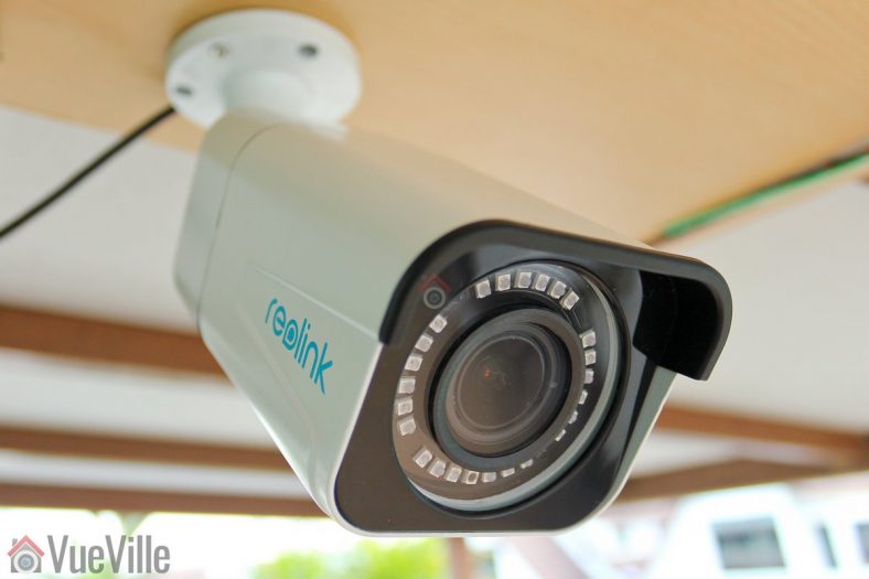
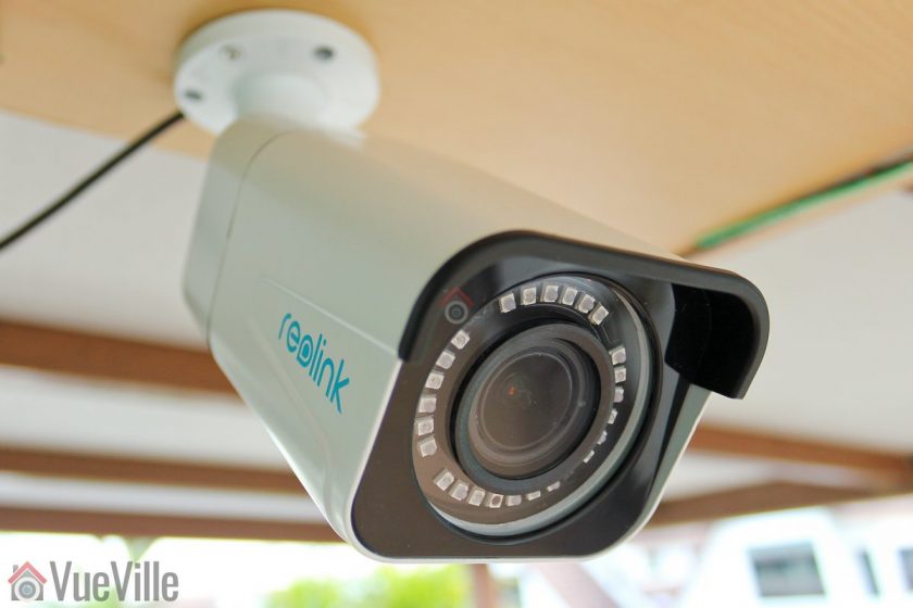
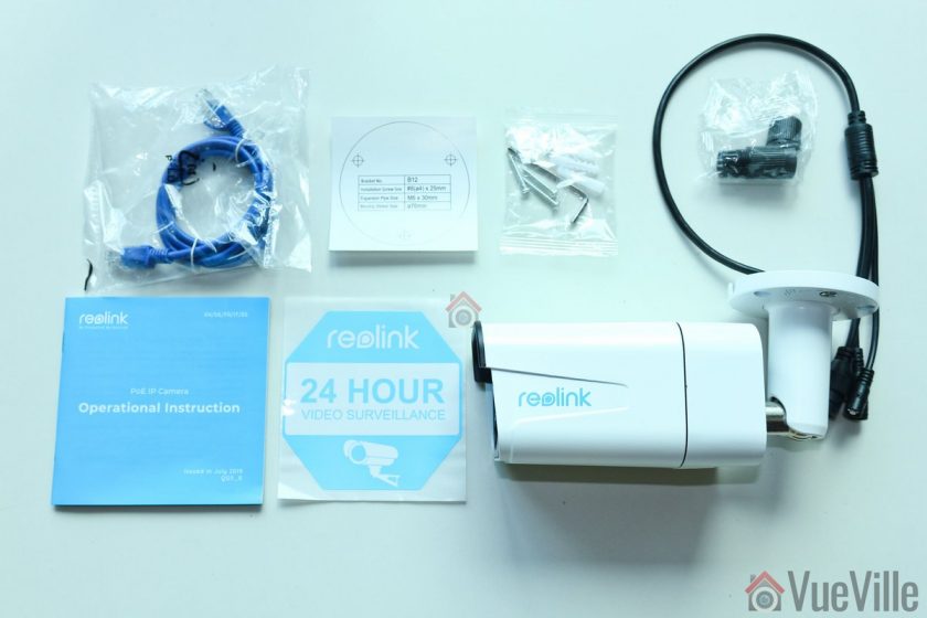
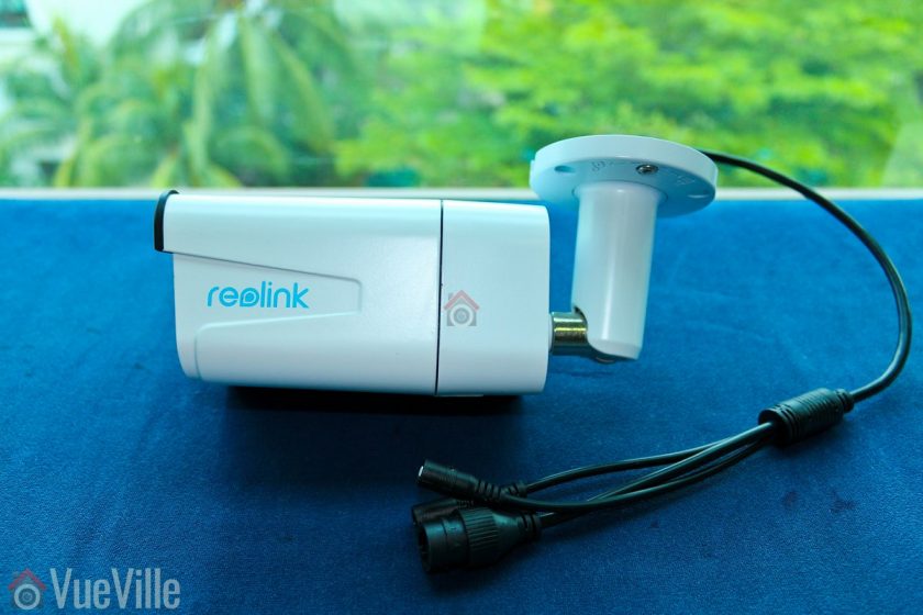
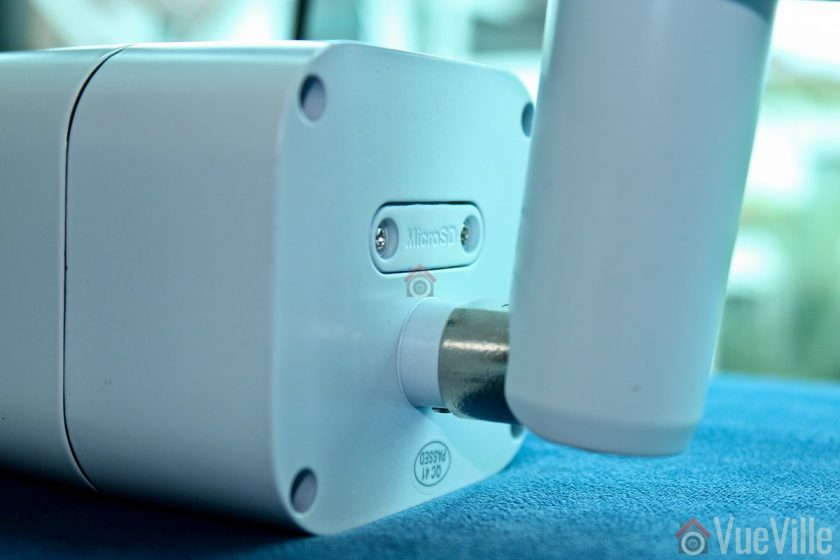
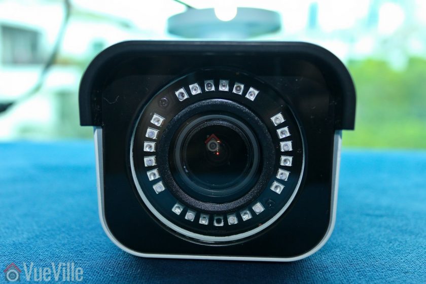
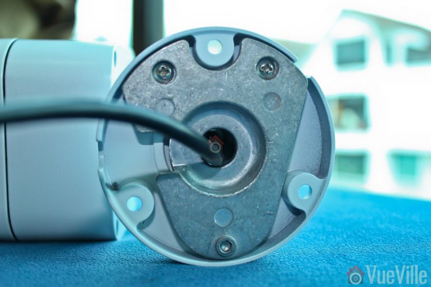

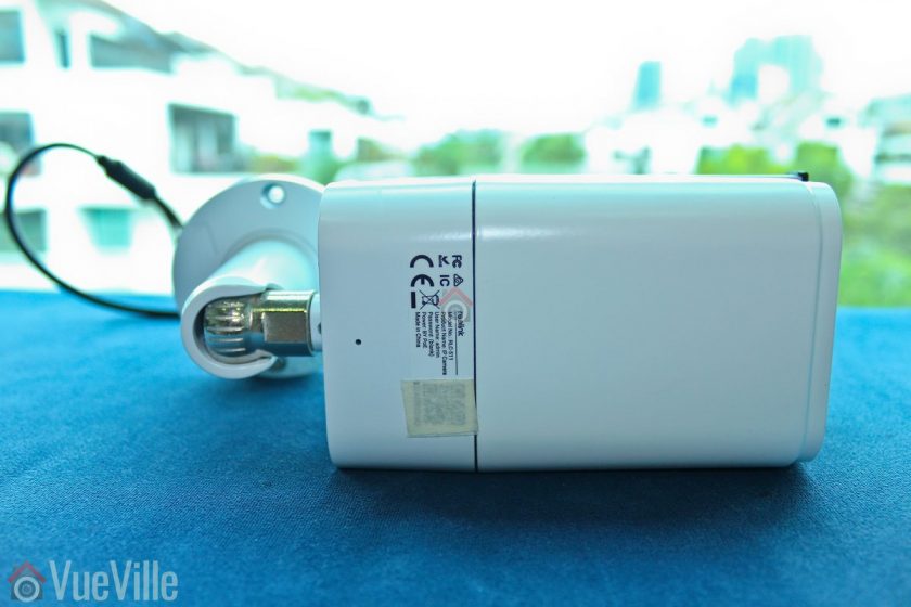
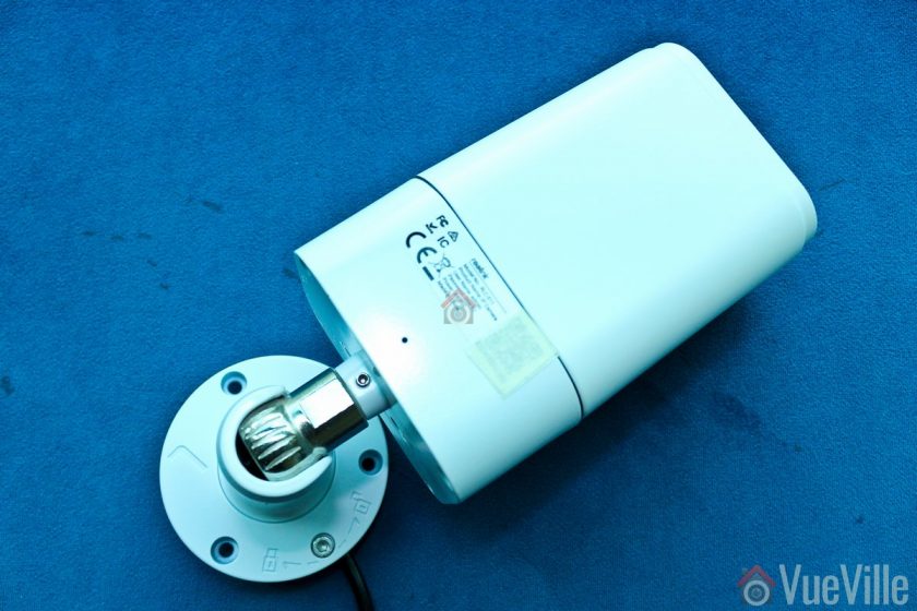
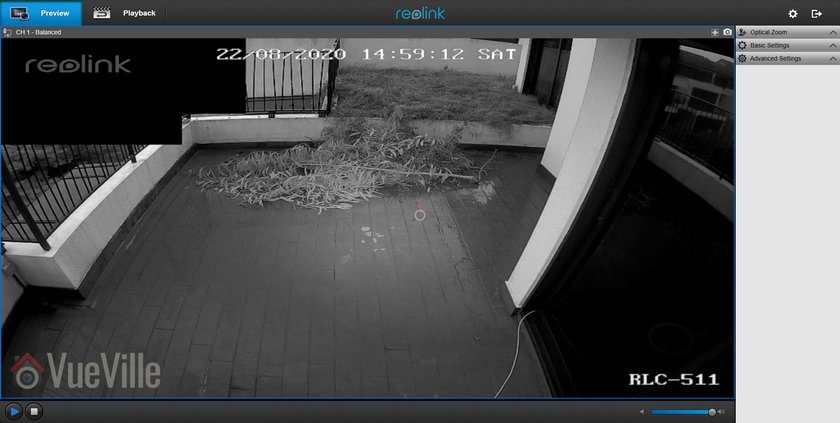
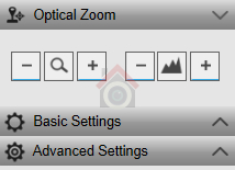
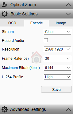
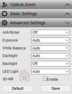
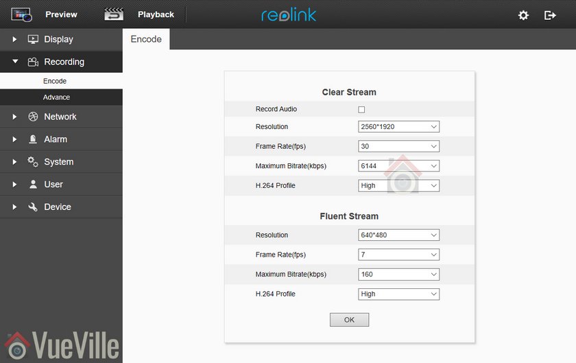
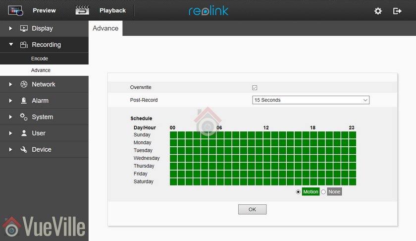
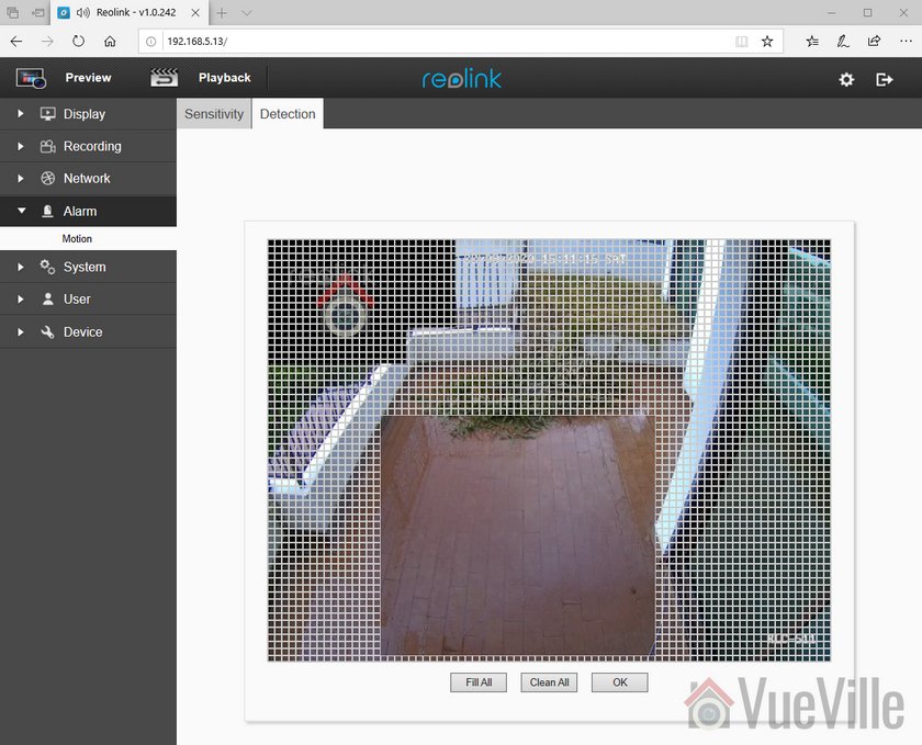
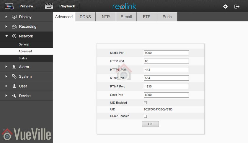
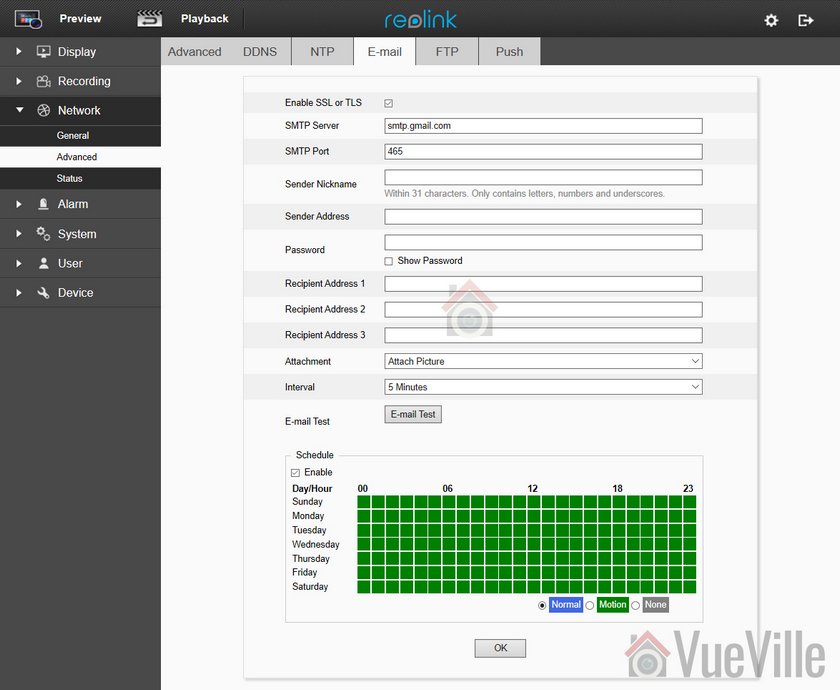

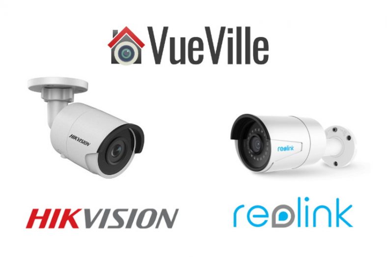


 Smart power plugs are perfect for turning dumb devices in your smart home into truly useful smart devices.
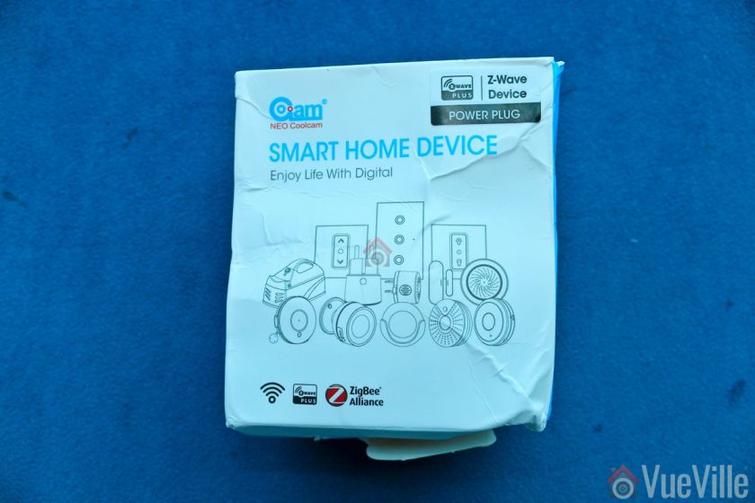
 The back of the box lists the main specifications of the sensor.
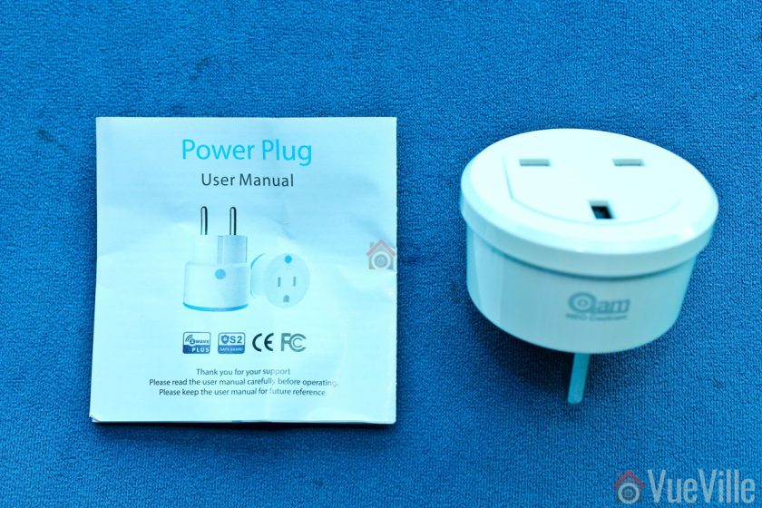 Opening the box, we find the following:
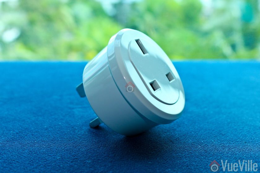
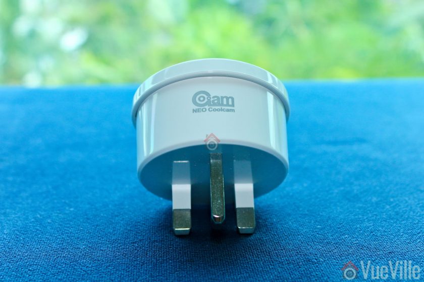

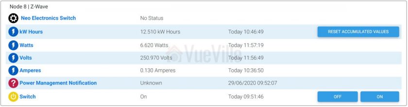 The first device is the parent device and the one where you configure settings such as Z-Wave parameters and polling intervals. Then we have the kW Hours device which stores cumulative energy usage. Then there are the usual Watts, Volts and Amperes devices which are used to calculate energy usage. The Power Management Notification device is next and this is where current overload warnings are shown. The switch has a maximum load current of 16A and of the load current exceeds this limit, the switch will automatically cut off, send a warning to this HS4 device and flash the red LED every 1 second. Finally you have the actual on/off switch control.