If you are thinking of setting up a Zigbee network for your Home Assistant installation, the USB dongle (co-ordinator in Zigbee-speak) you choose will have a significant impact on how reliable your network ends up being. Which in turn impacts how much time you spend trying to troubleshoot your smart home!
That’s why I recommend choosing your co-ordinator software first – Zigbee Home Automation (ZHA) or Zigbee2MQTT. Then pick a Zigbee dongle that is supported properly by your choice of co-ordinator software. Not all Zigbee USB dongles are supported by both.
If you are going with ZHA which is the default integration in Home Assistant, the Aeotec Zi-Stick is a new option from a smart home company that has been around for a long time. My Z-Wave network has always been powered by Aeotec – initially by the Z-Stick Gen 5 for many years, and now by the excellent Z-Stick Gen 7. The Zi-Stick is Thread-ready and so also supports Matter through a potential future firmware update.
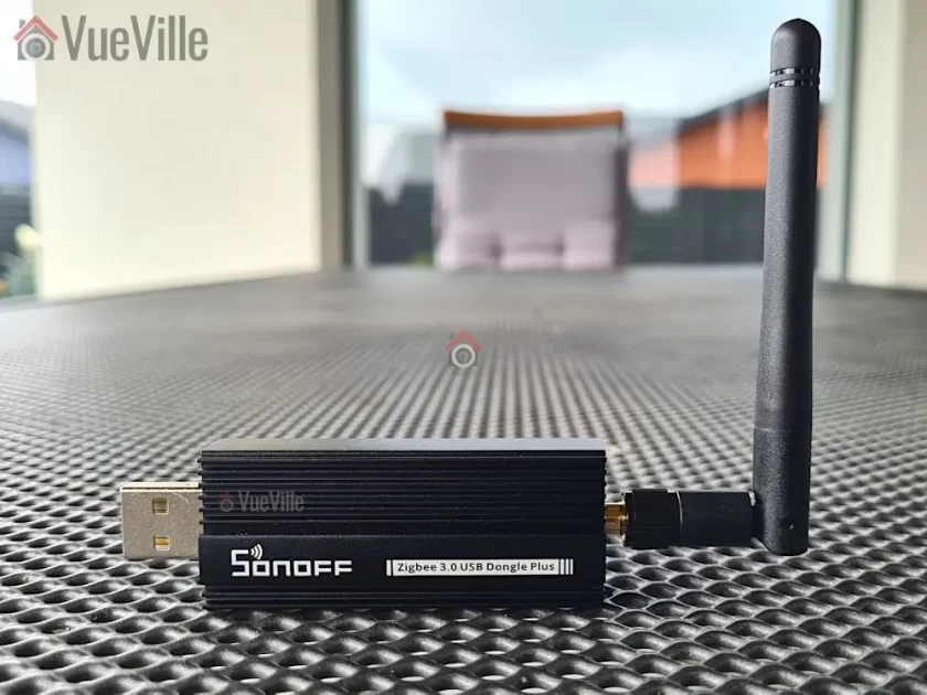
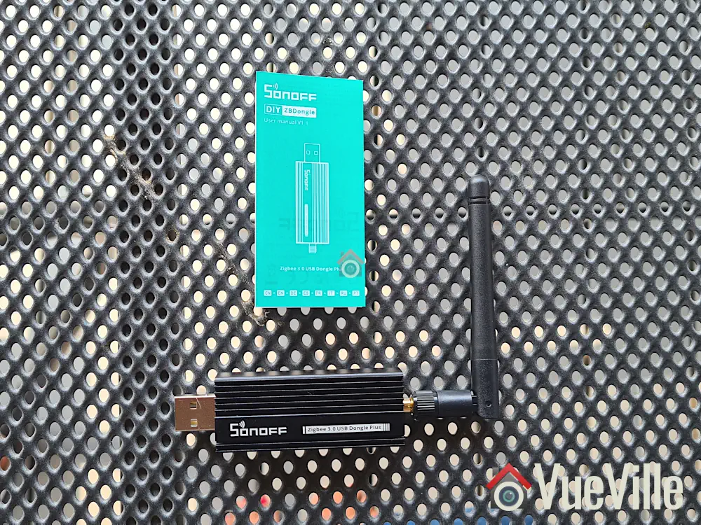
So let’s take a closer look at how the Aeotec Zi-Stick performs and how it compares to my current Zigbee USB dongle – the Sonoff Dongle-P.
A quick note: As an Amazon Associate I earn from qualifying purchases. This post contains affiliate link(s). An affiliate link means I may earn advertising or referral fees if you make a purchase through my link, at no extra cost to you.
Aeotec – who are they?
The Aeotec brand used to belong to Aeon Labs, a company that was founded in 2006 and based out of Silicon Valley. Aeotec is now headquartered in Hamburg, Germany. In 2018, they acquired the German automation brand Popp.
Zigbee Basics
If you’re new to the world of Zigbee like I am, here’s a primer on what you need to know.
Just like Z-Wave, Zigbee is also a mesh wireless protocol. This is one of the best things about Z-Wave that allowed me to create a strong reliable mesh network among all my Z-Wave devices. This is not possible with Wi-Fi or Ethernet where each device requires a direct connection to the router (although multiple WAPs can somewhat alleviate this).
So what does this mean in practice? Suppose your Zigbee coordinator sits in the garage with the rest of your tech gear, like mine is. And at the other end of your home, you want to place a temperature and humidity sensor like the Sonoff SNZB-02.
With Wi-Fi, you would need to be within range of your Wi-Fi router or have a WAP nearby. With Zigbee again the ideal scenario is if the sensor can connect directly to the Zigbee coordinator. But if its not, the mesh network comes into play. Most mains powered Zigbee devices such as smart bulbs or smart relays are able to act as ‘routers’ by relaying signals between the coordinator and other Zigbee devices. Do note that being mains powered does not automatically make a Zigbee device a router!
So our battery powered sensor can connect to the nearest Zigbee router and thus communicate with the coordinator. Thus our sensor here is an ‘end device’. Such battery powered Zigbee devices are usually not able to act as routers.
Now the biggest downside of Zigbee is that it uses the same frequency as 2.4 GHz Wi-Fi. This creates the potential for interference between your 2.4GHz band Wi-Fi network and your Zigbee network. I have learnt after much research (Metageek is an awesome resource) and quite a bit of fiddling that the best way to ensure your Zigbee and WiFi networks can coexist is by ensuring the specific frequencies (i.e. channels) they use do not overlap.
One thing to watch out is that the ‘channel’ numbering that WiFi and Zigbee use are similar and so you may think the frequencies won’t overlap. But they do! For example it may seem that Zigbee channel 11 uses the same frequency as Wi-Fi channel 11, but they don’t! In fact, Zigbee channel 11 overlaps Wi-Fi channel 1. The Metageek resource linked above explains it very well.
So my suggestion is:
Put your WiFi access points on channel 1 (if you have more than one WAP, use 6 for the one that’s furthest from the Zigbee coordinator and 1 for the WAP that’s closest to the Zigbee coordinator).
Put your Zigbee coordinator on channel 25 (or 20 if you are in the US).
This configuration ensures minimal overlap between your Wi-Fi network and the Zigbee network.
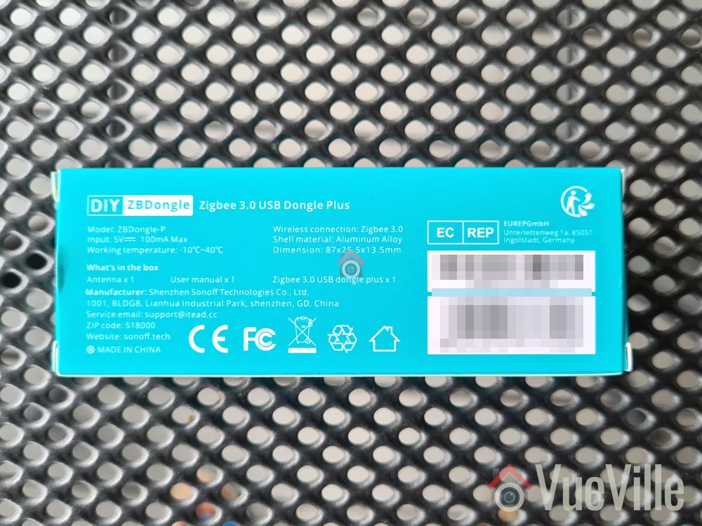
What’s in the Box
The Aeotec Zi-Stick box consists of the Zi-Stick USB dongle itself and a user manual.
Specifications
[table id=92 responsive=scroll /]
Taking a closer look at the Aeotec Zi-Stick
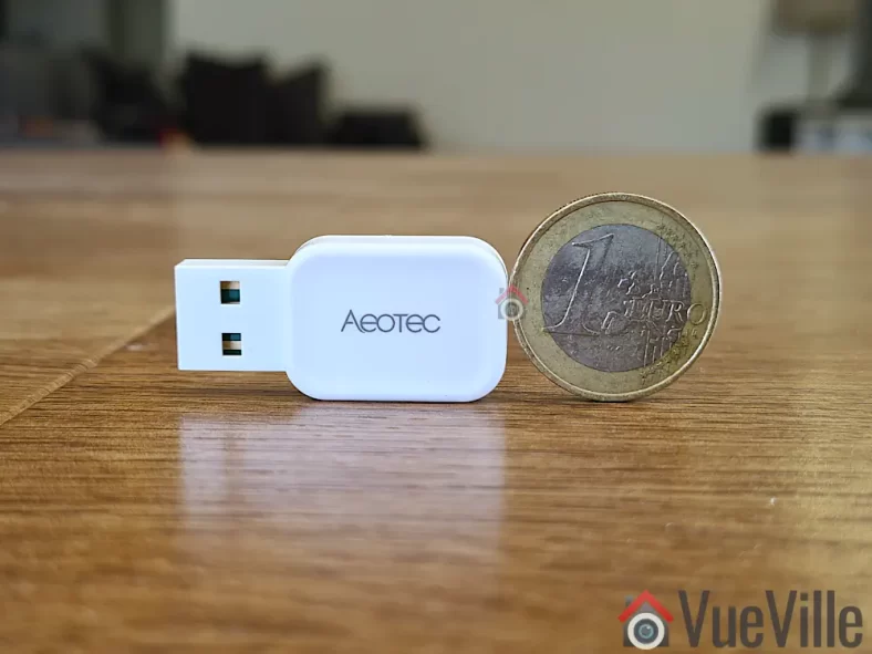
Just like the Gen7 Z-Wave Aeotec Z-Stick, the Zi-Stick is tiny. Compared to the Sonoff ZBDongle-P, it is less than half the size at at just 37 mm long and 17 mm wide.
The body is an all-plastic affair but feels sufficiently strong and seems built to last. After all, it is going to remain plugged into your smart home controller for the whole of its working life.
The front side simply sports the Aeotec logo whereas the rear side shows details such as the model number and applicable certifications.
The USB-A port should be plugged only into a shielded extension cable on a USB 2.0 port. USB 3.0 ports can cause interference with Zigbee networks, and is probably the root cause of many complaints about poor reliability when using Zigbee USB dongles.
Aeotec says this on their website: “Zi-Stick hardware is Thread ready and will be upgradeable via firmware update. With this future update, Zi-Stick will be able to control Thread Matter-based devices.”
Setting up the Aeotec Zi-Stick
Home Assistant offers 2 different integrations for Zigbee: the official Zigbee Home Automation (ZHA) built into HA, and the community integration called Zigbee2MQTT. I generally recommend Zigbee2MQTT because it has slightly wider device support and is generally quicker to add support for new devices as well. Unfortunately the Zi-Stick is officially supported only in ZHA, so that’s what we will be using for this review.
To briefly recap my HA setup, I have my primary HA server in the garage and a remote Raspberry Pi4 at the center of my single-floor home. The remote RPi4 runs ZWaveJS and Zigbee2MQTT as Docker containers, with an Aeotec Z-Stick for Z-Wave and Sonoff ZBDongle-P for Zigbee.
Since ZHA is part of HA, I decided to use the Aeotec Zi-Stick with the HA server in the garage. I plugged it into an extension cable off a free USB 2.0 port of the HA server (a NUC11i5 Mini-PC).
Plug in the device into your Home Assistant. Make sure you use a USB 2.0 port and a good quality extension cable. USB 3.0 ports cause interference and an extension cable minimises interference as well.
Navigate to Settings > Devices & Services > Add Integration
Type in “Zigbee Home Automation” and select ZHA from the list
Next you will see the “Select a serial Port” screen. I selected /dev/ttyUSB0 – USB serial. If you have other USB dongles plugged in it might say USB1 instead of 0. Just select that instead.
Next is “Network Formation”. I chose “Erase Network Settings and create a new network”. Wait for around 3 seconds and you should see a success message.
Click Finish, and you should now see the ZHA integration in the list. If you click on the ZHA device list, you can then see the Zi-Stick’ and its HA’s device page.
To ensure a solid and reliable Zigbee network, it is advisable to change the Zigbee channel to one that doesn’t interfere with Wi-Fi in your home. I have learnt after much research (Metageek is an awesome resource) and quite a bit of fiddling that the best way to ensure your Zigbee and WiFi networks can coexist is by ensuring the specific frequencies (i.e. channels) they use do not overlap.
One thing to watch out is that the ‘channel’ numbering that WiFi and Zigbee use are similar and so you may think the frequencies won’t overlap. But they do! For example it may seem that Zigbee channel 11 uses the same frequency as Wi-Fi channel 11, but they don’t! In fact, Zigbee channel 11 overlaps Wi-Fi channel 1. The Metageek resource linked above explains it very well.
So my suggestion if your using only the Zi-Stick in your home:
Put your WiFi access points on channel 1 (if you have more than one WAP, use 6 for the one that’s furthest from the Zigbee coordinator and 1 for the WAP that’s closest to the Zigbee coordinator).
Put your Zigbee coordinator on channel 25 (or 20 if you are in the US).
This configuration ensures minimal overlap between your Wi-Fi network and the Zigbee network.
What if like me you already have another Zigbee network in the home? Then I recommend you put the Zi-Stick on Zigbee channel 20 instead of 25.
Zigbee Pairing using ZHA & Wireless Range
To test the Zi-Stick, I decided to pair it with their latest Pico Switches that I have also reviewed separately in detail. Head over to that review to read more about the pairing process.
Here’s a network map produced by ZHA that shows the link quality and the routes between each device:
ZHA Network Visualisation for the Aeotec Pico and Pico Duo Switches
One Pico switch was installed in a concrete wall right next to the Zi-Stick. So that would naturally be the router through which the second Pico switch finds a connection to the co-ordinator. So everything is as expected in the network map above.
The second Pico Switch is 3 concrete walls away from the co-ordinator, but it still managed to establish a direct connection (strength 74/32 up and down) which is quite impressive.
Product prices and availability are accurate as of the date/time indicated and are subject to change. Any price and availability information displayed on https://www.amazon.com/ at the time of purchase will apply to the purchase of this product.
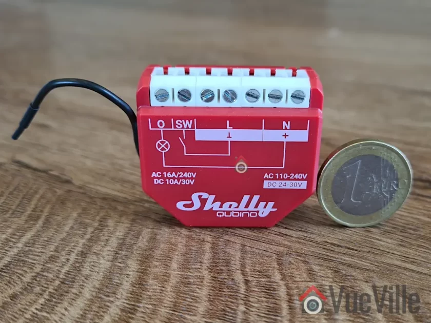
I have been on a smart lighting and smart relay installation spree in my new home. So far I have got the Wi-Fi Shelly 1PM, Shelly 2.5, and the Z-Wave based Shelly Qubino Wave 1PM set up in Home Assistant. So what’s missing? Zigbee relays!
I have been using Zigbee devices such as Sonoff sensors & Ikea Tradfri bulbs in my home. So I was happy to receive retail samples of the brand new Aeotec Pico and Pico Duo Zigbee relays from Aeotec for this review.
A quick note: As an Amazon Associate I earn from qualifying purchases. This post contains affiliate link(s). An affiliate link means I may earn advertising or referral fees if you make a purchase through my link, at no extra cost to you.
How to use this Smart Relay
Since my home already has dumb switches and (mostly) dumb ceiling lights that I do not want to replace, it made sense for me to retrofit my existing dumb switches to make them smart.
Installing a smart relay behind an existing switch or power socket in the wall is a good choice for when you want to keep your existing physical switch or socket but want to remotely control or measure an electrical load (light/fan etc.) connected to that switch.
This way you can control the connected load through the physical switch as well as remotely through the smart relay using Home Assistant or any other Zigbee compatible smart home platform.
Since the Aeotec Pico and Pico Duo switches work as Zigbee repeaters, I will be using it to strategically extend the wireless range of my Zigbee network as well. Just like Z-Wave, only mains powered Zigbee devices are capable of being repeaters, so an in-wall relay is a great fit for this purpose.
As usual, I will be using these smart relays together with Sonoff Zigbee motion sensor for motion-activated lighting. The idea is that Home Assistant will turn on the lights through the relay whenever motion is detected and after some time switch them off. Of course if anyone wants to turn on the lights physically, the existing physical switch will continue to function exactly as it always has. But I also then have the added bonus of Home Assistant being aware fo the status of the switch and turn off the relay if someone forgets to turn the lights off! I can also use it as part of my night mode routine to ensure all lights are off at bedtime.
What’s in the box
The Pico Switch and Pico Duo Switch have similar packaging.
The box contents are similar as well:
Pico Switch
2x WAGO clamps
1x DIN Rail Mount
User manual & Safety information
Specifications of the Aeotec Pico Switch
[table id=91 responsive=scroll /]
Physical Design
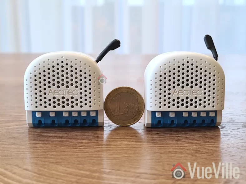
Visually both the Pico and Pico Duo Switch look identical from the front. Its only on the rear that you see the differences such as the model numbers. They both measure 44 x 40 x 21.5mm, which is slightly larger than the Z-Wave based Shelly Qubino Wave 1PM I reviewed recently. If your wall box is very small, this is something to keep in mind.
The Action button is a multi-purpose button, and apart from Zigbee pairing it even acts as an ON/OFF button for the relay. The ventilation holes are prominent on both the front and the back of the switches.
As this is a brand new product, it is not supported in my preferred Zigbee integration for Home Assitabt – Zigbee2MQTT (Z2MQTT). However, it is fully supported in Home Assistant’s official Zigbee software called Zigbee Home Automation or ZHA.
Installation & Wiring
The user manuals accompanying the Pico switches shows the wiring diagram for using the relay in a typical 1-way scenario.
With the help of a professional electrician, I installed the Pico Switch in a 2-way scenario in my laundry room. This is right next to the foyer where I have a Shelly Qubino Relay installed, so it will be fun to compare the responsiveness of these different relays later on.
The Pico Duo Switch was added to the existing switches for my living room LED lights – these are non-dimmable LEDs built into the ceiling. A Shelly 2.5 would be wasted here since the LEDs are dumb lights, so a relay without detached switch feature such as the Pico Duo is perfect here.
I recommend the Shelly 2.5 as the retrofit option if you have a smart bulb connected to a dumb switch that you want to retain. Using the detached switch feature of the Shelly 2.5 lets you keep the smart bulb powered on, and the physical switch becomes a virtual switch that you can then automate in Home Assistant.
In both instances, the external connected switches are double-pole toggle switches which is also the default setting in the Pico relays. You can always force the Pico relays to automatically detect the type of connected switch if you use something else (such as a momentary switch).
The terminal blocks of the Pico Switches are of the clamp type which makes wiring a doddle. There are also extra terminals for live and neutral connections. That makes it much easier to fit the relay into tight spaces without having to add extra Wago connectors.
Aeotec Pico Switch InstallationAeotec Pico Duo Switch Installation
Adding the Pico Switch and Pico Duo Switch to my Home Assistant Zigbee network
The best time to add the Pico relays to a Zigbee network is after wiring and before you put the relay into the wall. This is because there is a very helpful LED indicator on the relay that shows whether the relay is in pairing mode or not.
There are 4 ways to put the relay into pairing / inclusion mode:
Using the Touchlink feature which lasts only for 3 seconds after relay power-up
Pairing the relay within 180 sec of powering on the relay as it will be in pairing mode
Using the Action button (only possible before the relay is closed up behind the switch)
Using the external switch connected to the relay
I chose the action button method and these are the steps I followed for both the single and dual Pico relays:
Wire the Pico relay as per the wiring diagram. Wiring took more than 3 minutes after initial power on and during these 3 minutes the LED flashed quickly, after that the relay exited pairing mode by itself and the LED went into slow breathing mode.
Enable add/pairing/inclusion mode on your gateway (Zigbee Home Automation or ZHA).
Press the action button once, the relay is now in Zigbee pairing mode an the indicator LED will start flashing quickly.
Wait for a bit and when pairing is successful the LED indicator will enter regular light mode (constant blue light or off based on the state of the Pico Switch). If the LED is off, just click the action button to turn on the relay.
Here’s the success message I received in ZHA:
If pairing fails, Light Indicator will return to a slow breathe animation. There are a few things you should check before pairing again:
Ensure you have a strong Zigbee mesh network – placing a wired Zigbee repeater device nearby will help.
Do a factory reset by pressing and holding the action button for 17 seconds
Features
Looking at the device page in ZHA, we can see the various controls and sensors exposed by the Pico Switch and Pico Duo Switch:
Pico Switch – Device Page in ZHAPico Duo Switch – Device Page in ZHA
The Pico relays support power consumption measurement and energy measurement. In ZHA, you also get some useful power-related sensors such as voltage, current, and AC frequency. These sensors enable the ‘Surge protection’ feature which will shut off the relay in case of a sudden mains power surge.
These relays also support overheat protection by using a built-in temperature sensor. You may have noticed that the device temperature value reported in ZHA in the screenshots above look wrong at 0.3 deg C, and they are! There is a bug in the ZHA device handler so it shows the temperature divided by 100. For now, the workaround is to create a virtual sensor with the value multiplied by 100.
When it comes to configuration options, the ZHA interface allows us to define the startup behaviour of the switch, say after a power failure. The default is previous state, and thats where I would leave it.
Performance
I like to look at the following areas when I judge a smart relay:
Local operation,
Responsiveness (both over the Zigbee network and the physical switch),
Reliability,
Power Measurement & Energy Monitoring,
Signal strength & Repeater feature,
Safety, and
Cost
I used a NUC running the Home Assistant ZHA integration together with an Aeotec Zi-Stick placed in the garage. The Pico Switch is one concrete wall away from the co-ordinator and the Pico Duo is another concrete wall from the Pico. There are no other devices on this Zigbee mesh network.
Local operation
Zigbee allows for fully local operation without any need for Internet access or cloud reliance. So that’s an easy one, full points here just like a Z-Wave relay!
Responsiveness
This is probably one of the most important criteria to judge a smart relay on. Whether you are controlling the relay over Zigbee or via the connected switch, you want the relay to respond instantaneously.
I tested the Pico Switch relays extensively and found them to be very responsive with zero lag/delaywhen controlled over Zigbee.
Okay, how about using the connected physical switch? Let’s take a step back and define the context here. Any relay that supports connected switch actions other than a single ON/OFF command, such as double press, triple press, press and hold etc. will have a delay programmed into it so that it can decide whether a switch press is really a single press or will be followed by more quick press to turn into a double or triple press.
The Shelly Wi-Fi relays on the other hand have virtually zero lag/delay because by default it doesn’t wait to see if a press turns into an extended action.
Most smart relays however do support extended actions. For example, the Shelly Qubino Wave 1PM I reviewed recently is a Z-Wave smart relay which supports extended actions. But it has a rather annoying half a second delay when using the physical switch connected to it. Moreover, the delay is not adjustable.
So how do the Pico relays compare? Both the Pico and the Pico Duo relays do have a slight lagwhen controlling a connected load using the physical switch connected to the relay. Since this is not mentioned in the specifications, I asked Aeotec and they said the relays are programmed with a ‘maximum capture interval’ of 300 ms. This means the relay will wait for up to 300ms before turning on the connected load so that it can detect a double-tap action in the meantime. This is much better than the 0.5 sec delay I saw on the Shelly Qubino Wave 1PM but again it cannot be customised.
In practice I found that this slight delay in the Pico switches is tolerable and was not too confusing for little children or guests who were not used to a delay between turning on a switch and the light turning on.
Reliability
After using the Pico and Pico Duo Switches for over 1 month, reliability has been excellent. The smart relays have never gone offline, become unavailable, or failed to respond to commands from Home Assistant.
Power Measurement & Energy Monitoring
One of the biggest advantages of the Pico relays is the power and energy measurement feature. The power sensor starts reporting immediately after the relay is turned on. There’s hardly any delay and this is very useful for triggering other automations for the device you are monitoring.
Signal strength & Repeater feature
ZHA Network Visualisation for the Aeotec Pico and Pico Duo Switches
Opening the built-in visualisation feature of ZHA lets us check the signal strength and which devices are acting as routers.
As expected, the Pico Switch which is closer to the co-ordinator has connected directly to it, and the Pico Duo Switch which is further away has connected through the Pico which is acting as a router. Of course the Duo itself is also recognised as a router device. Sweet.
Signal strength with the Zi-Stick as the Zigbee co-ordinator looks solid across the board with the link quality hitting the maximum possible 255. Something I have never seen with my other Zigbee network running off a Sonoff Dongle-P.
Safety
The Pico & Pico Duo Switch relays meet all the safety requirements for such devices in the EU.
The relays have both overload protection as well as overheating protection.
Cost
I have found that while Aeotec products can sometimes be more expensive than competing products, they have high quality levels and that’s what you are paying for. Please check the latest prices using the Buy Now links at the end of this article.
The In-Wall Relay Competition
Sonoff has several Zigbee based relays, however I do have quality concerns when it comes to Sonoff devices that would go into my AC power wiring. The other popular option is Aqara which I have not tested personally but can be found a bit cheaper than the Aeotec Pico Switch.
If you need a Zigbee relay that can switch up to 16A, act as a router, has power measurement and don’t mind a 0.3 second delay when using the physical switch, the Aeotec Pico and Pico Duo Switch relays re solid choices. Of course, there is zero delay when controlling the connected switch over Zigbee.
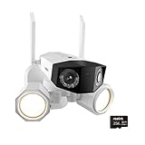
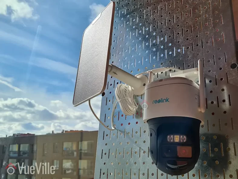
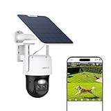
I have always wanted a 4K Power over Ethernet (PoE) security camera with built-in LED floodlights. It’s possible to install separate smart floodlights for my existing cameras, but you just can’t beat the convenience of a single package that works on Power over Ethernet (PoE). No extra power supply or wiring needed!
Reolink sent me the Duo Floodlight PoE to review and I have been putting it through its paces. There are 2 versions of this security camera – this PoE model we are reviewing today and a Wi-Fi model. Apart from having 4K resolution, 2 bright floodlight LEDs, it also has dual lenses with 180º field of view and smart detection that can turn on the floodlights whenever a person, animal or vehicle is detected. It can also work fully locally with any ONVIF-compliant NVR, Home Assistant or Frigate NVR. No cloud reliance & no subscription!
Sounds too good to be true? Well, we are going to look at the features of this camera, setting up with the Reolink app, Home Assistant, Frigate NVR, floodlight and motion detection performance, video & audio quality and how well it works with our VueVille DIY Home CCTV system and our DIY Smart Home Automation System! Let’s get started!
A quick note: As an Amazon Associate I earn from qualifying purchases. This post contains affiliate link(s). An affiliate link means I may earn advertising or referral fees if you make a purchase through my link, at no extra cost to you.
Video Review
If you’d prefer this post in video format, here’s an in-depth video review:
How to use this camera and my setup
There are several ways to use the Reolink Duo Floodlight camera:
It can work as a fully standalone security camera. If you use its built-in microSD card you can also enjoy the built-in NVR feature accessible through the Reolink mobile app or desktop app.
Since the camera supports ONVIF and RTSP, you can also use the camera with any ONVIF compliant NVR or PC or NAS-based NVRs (like Frigate NVR) but not all features may be supported.
Of course you can always connect it to Reolink’s own NVR models and all the camera’s special features such as floodlight control will be available too.
If you prefer, you can always set the camera to save clips to an FTP server, but the built-in NVR feature will not be available in the Reolink mobile and desktop apps.
The camera will also work with Home Assistant using the Reolink Integration.
Personally I have the Duo Floodlight connected to Home Assistant and to Frigate NVR which does AI object detection. I also have the Duo Floodlight configured to upload smart motion detection clips to an FTP server on my local network. More on that in the Frigate and FTP sections below.
What’s in the box
The box contents list of the Reolink Duo Floodlight:
Reolink Duo Flodlight 4K IP camera
Floodlights
Mounting plate
Mounting hole template
Installation and operation guide with photos
1 metre Ethernet cable
Screws, rawl plugs
Surveillance sign
UK and EU regulatory compliance certificates
Specifications
[table id=89 responsive=scroll /]
Design & Features
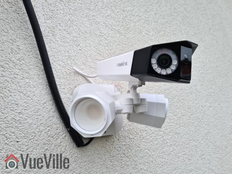
The Reolink Duo Floodlight looks exactly like what you would imagine if you have seen the regular Duo camera before. Basically it’s the Duo dual-lens camera that is attached to the floodlight accessory that is also available for purchase.
Indeed, it has been possible to buy the regular Duo camera and the Floodlight separately and link them to with each other through the Reolink app. However the floodlight was not controllable through 3rd party interfaces like the Home Assistant integration or any other smart home system. So the Duo Floodlight addresses a very relevant use case where you can trigger the floodlight by any other sensor or device in your smart home, or any other Reolink camera, not just the Duo camera it is attached to.
In the box, the camera and the floodlight come packaged separately. Everything that you need to mount & install the camera on a masonry wall is included in the box, there’s even an Ethernet cable!
Let’s take a closer look at the camera now. The body is the same as the regular Reolink Duo camera with a dual-tone black and white metallic casing. The camera has a smart image stitching feature whereby it automatically seamlessly stitches the streams from each lens to produce a single 4K stream with 180-degree field of view.
Unlike the previous generation Duo, this camera will not let you access each lens’ 2K stream individually. So whatever you plan to do with the video stream, make sure your hardware can handle a very wide resolution of 4608 x 1728. I use the Duo Floodlight with Frigate NVR and as long as you don’t place the camera too high up which distorts the camera view, Frigate object detection works very well even at this ultra-wide resolution (more on that in the Frigate section below).
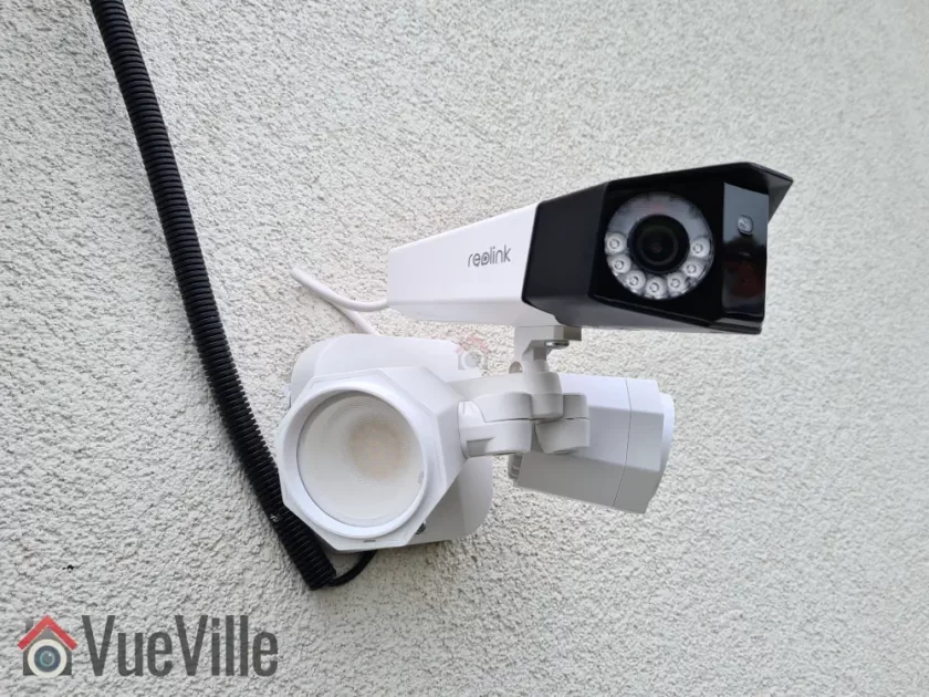
For night vision, each of the 2K lens have 7 IR LEDs around it (850nm type). The 14 IR LEDs together give a black and white night vision range of 30 metres (98 feet).
The day/night light sensor for the auto IR cut filter is placed between the two lenses. This lets the camera automatically switch between day-time colour vision and night-time IR. The microphone is placed just below the day/night sensor.
On the top of the camera, there is only a mounting point in case you want to place the camera below the floodlights for some reason (the recommendation from the manual is to place the camera over the floodlights instead).
On the underside of the camera, we see a removable cover for the microSD card slot and the reset button, the mounting point for attaching the camera to the floodlights and the down-firing speaker. Together with the mic, the speaker lets you have a 2-way conversation with anybody near the camera.
The microSD slot takes cards of up to 256 GB in capacity, which is pretty standard these days. If you don’t have an NVR or don’t need one, the camera has built-in NVR feature using the microSD card slot. Since the Reolink Duo Floodlight supports only H.265, make sure your browser can handle this format for playing back video clips etc.
So how do we connect the camera to the floodlight? That’s where the adapter fixed permanently to the camera comes in. It has a DC power port, LAN port and a two prong LED connector port.
Let’s take a look at the floodlight now. The 40 LEDs together provide 1800 lumens of illumination with a colour temperature of 4200K which is cold white. The LEDs consume 15W of power by themselves. That’s why the camera and floodlights together are rated at 24W power consumption. So you can see why this camera needs a PoE switch that offers the 802.3 at standard (and not just 803.3af PoE). 802.3at provides up to 25W of power whereas 802.3af can do only 15W.
Each of the floodlights are individually adjustable so that you can point them anywhere you want. The camera can also be adjusted up, down, left and right using the included Allen key. You can also adjust the tilt angle of the camera.
When assembled together and plugged into the LED port, this is what the end product looks like:
Camera Mounting
The recommended height for installing security cameras is between 8 – 10 feet. If you have ever tried installing a large camera at that height while on a ladder, you know its difficult. Thankfully Reolink has thought this through properly and mounting the camera can be done in stages.
Screw the camera and the floodlight together as shown earlier
Connect the cable from the LED to the camera adapter
Mark the screw holes using the provided drill template
Drill and install the mounting bracket. My house is a North European new build, it has a thin façade with 25 centimetres of insulation block behind it. So I have to use special anchors & screws that are not included with the camera.
Hook the safety clip
Connect the Ethernet cable from your PoE switch, and the DC cable (if not using PoE)
Place the camera on the bracket
Screw in the final screw and you’re done!
Make sure your switch can provide enough power for the camera to work, that’s up to 24 Watts at night when the floodlights are on. I use a Lanberg 802.3at PoE switch which can provide up to 30W per port. That’s plenty of power for the camera.
Reolink Duo Floodlight PoE Setup
By default when you plug it into your network, it will accept an IP address provided by your DHCP server. As the Reolink Duo Floodlight is capable of fully local standalone operation, an Internet connection is not required for either camera setup or operation (except push notifications).
So you are not forced to follow a software installation process but several methods are available for adjusting the camera and for using the advanced features such as AI motion detection, floodlight control, clip playback etc.
This is my preferred method of managing the camera settings. Since the camera admin page uses HTML5, you can use any modern web browser such as Safari, Chrome, Firefox or Brave.
With the Reolink Duo Floodlight, I had to adjust the image stitching settings slightly to get the images from the two lenses to line up perfectly. This is found under the image stitching setting on the live view landing page. I also set the privacy mask feature to mask off some houses in the background.
However, the web admin page wouldn’t allow me to live-view the main 4K stream in my browser complaining that the system was not powerful enough. This is definitely not true, its a pretty powerful gaming PC with a Ryzen 12 core CPU, tons of RAM, NVMe drive, and an NVIDIA 1660 Super video card.
There is a button to control the floodlights but it didn’t work. Neither did the audio alarm button work. You also cannot access the 2-way talk feature from here.
Setup using the Reolink Desktop App
The Reolink Desktop app is ideal for live-viewing the main stream (4K resolution), and for using the built-in NVR feature of the camera.
The live-view feature is especially useful if you use only Reolink cameras and would like a multi-camera view – the software can display up to 36 cameras simultaneously.
Also there is a very nice toolbar at the bottom of the app that enables 2-way talk, controls the floodlight, sound the siren, take snapshots, or record clips.
However there are some oddities – I couldn’t find the image stitching settings in the Reolink desktop app, which was available in the web admin page.
If you are using the camera for motion detection, it is worth adjusting the smart detection sensitivity and setting up the features such as minimum object size and motion masks.
Both the desktop and mobile apps allow you to set these up. Reolink calls motion masks No-Detection Zones. So you don’t need to rely on privacy masks if you don’t want the camera to detect motion in one area. This is very useful for areas like the footpath or road in front of your driveway, because you are not interested in the people or cars on the road, just the ones that enter your driveway. All of these adjustments will help reduce false alerts massively.
The floodlight behaviour can be controlled in detail – I like to leave it at the default Night Smart Mode setting where it turns on only at night when it detects a person. You can record audio on your clips if you like. As usual, the recording behaviour and schedule can be customized. And you can scare people away by automatically sounding the siren along with the floodlights turning on.
Setup using the Reolink Mobile App
The Reolink mobile app is needed if you want Reolink’s push notifications to work. You will also need to turn on the UID (P2P) feature and give the camera internet access.
Personally I do not use the Reolink mobile app in my setup because I use the excellent Frigate NVR lovelace card which works beautifully in my HA dashboard and Home Assistant mobile app for actionable notifications. However for the purpose of testing the app for this review, I enabled the camera’s UID feature and gave it Internet access.
The mobile app is pretty good and very easy to use. It never crashed over the many months I have been using it on my Samsung S20.
There’s also a new beta feature in the mobile app called MotionMark which will draw a bounding box around the object that has triggered the motion alert. Very useful for troubleshooting false alerts etc.
Setup Reolink Duo Floodlight PoE in Home Assistant
Personally I use the Reolink integration to control all aspects of the camera, after using the web admin page for adjusting things such as image stitching, stream settings such as fps, privacy masks etc.
Since this was the first Reolink camera I was installing that was supported by the official Reolink Integration, I had to add the camera as part of the installation process of that integration in Home Assistant:
Ensure your firewall allows your Reolink camera to reach the Home Assistant server
Ensure the user you create in the camera interface for the integration to use is an administrator account
Enable the http port option under the camera’s network settings (its off by default)
Install the Reolink integration from Settings>Devices>Integrations
Enter an admin username, password and the IP address of the Reolink Duo Floodlight PoE
Wait a couple of minutes until you get the message saying the camera configuration has been successful.
Head on over to the device page from Settings>Devices>Integrations and treat yourself to this amazing integration that gives local access to the whole camera. All the important settings and sensors are available so that you can control them manually or programmatically through Home Assistant!
You will need to enable the main stream entity manually if you need it. Regarding performance, I didn’t notice any delays while controlling the camera through this integration. Any camera switch or setting you change through any other method will be reflected in the integration as well. Just make sure the http and https ports are enabled in the camera config.
Setup Reolink Duo Floodlight PoE in Frigate NVR
I have Frigate NVR set up on a NUC11 mini-pc and an M.2 Coral Edge TPU, and I use the H.265 streams for detection and recording whenever possible. Here are the host system specs in case you are interested:
Intel NUC11TNKi5 with Iris XE integrated graphics
32 GB RAM
2 TB Samsung 970 Evo NVMe SSD
Coral Edge TPU (M.2)
Frigate 0.12 configuration: Coral as detector, preset-vaapi for hardware acceleration (hwaccel argument)
Detection streams: Main streams resized to 1080p (I don’t use sub streams because they are generally not detailed enough to detect small animals like cats)
The Frigate docs do recommend using a Reolink specific configuration but I thought I would try it with just the standard setup above. I was very pleased to see that everything worked well out of the box.
For the detection stream, I set Frigate to resize the main stream to half of 4K resolution. I am using the main stream for detection because I found that the sub stream resolution is not high enough for accurate detection of small objects like cats. Not surprising because the camera has 4K resolution over 180 degree field of view, instead of say 110 degrees like a single lens camera.
Because my system is powerful enough to handle on the fly resizing, I am not forced to use the sub stream for detection. I also enabled the constant FPS option in the Reolink settings and set the i-frame interval (Interframe Space as Reolink calls it) to once every frame.
Here’s the configuration I use for ffmpeg in Frigate:
Setup Reolink Duo Floodlight PoE to upload clips to an FTP server
I have the Duo Floodlight configured to upload smart motion detection clips to my FTP server on my local network (not the Internet). Here’s how I have it configured using the mobile app (you can use the web admin page or desktop app also):
FTP Settings – click to enlarge
Don’t forget to specify the remote directory – in my case it is ‘upload’. This is because the default directory I have set for the camera’s FTP account is ‘/home/backyard_duo/ftp’ and I want the camera to place clips inside a folder called ‘upload’.
Secure FTP is supported by the camera.
Performance Testing
With a camera that has so many different features, it is a challenge to address every single use case. So I have decided to focus on those things that most people buying the Reolink Duo Floodlight PoE will care about.
During the daytime it should be able to quickly and accurately detect a person/animal/vehicle who is entering my property, send me push notifications, record a video clip to the SD card/FTP server/NVR.
During the night time, it should also turn on the floodlights whenever a person/animal/vehicle is detected.
Use the siren feature to scare away intruders/animals.
Use the 2-way talk feature to talk to the person/shout at the intruder when I am not at home.
It should not fail to detect people during the day or night!
No false alerts (even at the highest sensitivity for smart motion detection)
Advanced features: Home Assistant integration hat works well & Frigate NVR compatibility for accurate object detection without any fuss
Test Setup
I increased the sensitivity of the person detection to maximum so that we are fully testing how powerful the smart detection algorithms are.
For the daytime tests, I set the siren to sound so that we can see the precise moment at which the person is detected. Similarly for the night-time tests, the floodlights turning on indicate the precise moment of person detection occurring.
The test scene:
15 metres from the camera to the fence straight ahead
30 metres from the camera to the fence on the left of the camera
20 metres from the camera to the fence on the right of the camera
Smart Motion Detection, Floodlights & Video Quality
Our test scenarios comprised of a person walking across my 500 metre sq. backyard:
Entry from right (20 metres from the camera) and walking across the camera to the left,
Entry from left (30 metres from the camera) and walking across the camera to the right, and
Approaching the camera head on from the centre of the scene.
We conducted the above tests during the day and the night with no other camera’s IR or illumination present.
In the first 2 test scenarios during the daytime, the camera detected the person within 2 seconds of entering the scene. This was evident from the siren turning on & the push notification being sent. So we can confidently say that the camera can detect persons at a distance of 30 metres when the person is walking across the scene. In the final scenario of the person approaching the camera head-on, the person was detected at a distance of 10 metres (33 feet).
We then carried out the same tests at night-time. This is the real test of any camera’s motion detection as it has to rely purely on its Infra-Red LED for night vision. The moment of person detection was observed by noting when the floodlights turned on. Once again the person was detected within 2 seconds of entering the scene. So very similar to the daytime test results. In the final scenario of the person approaching the camera head-on, detection occurred at a slightly lesser distance of 7 metres (23 feet).
I tested the Reolink Floodlight Duo PoE extensively over a month and had only a single instance of an adult person being mis-categorized as a pet instead of person. The camera didn’t create any false positives nor did it fail to detect a person.
So in summary, the daytime smart detection is excellent and night-time smart detection is pretty good. The video quality is excellent during the daytime as one would expect from a 4K camera. Night-time video quality is more than acceptable especially with colour night vision thanks to the floodlights. Adding external IR illuminators will further improve motion detection.
Audio Quality (2-way talk)
We tested the Reolink Duo Floodlight PoE’s 2-way talk feature through the Reolink mobile app, both over Wi-Fi and 4G mobile data. I stood around 6 feet away from the camera and my wife was at the other end on the Reolink mobile app. Pressing the ‘tap to talk’ button on the app enables the feature.
My wife could hear me clearly and my voice was also clearly recorded on the motion detected clip that the camera recorded to my FTP server. My voice came through at a good volume at her end. Her voice was audible on the the camera’s down-firing loudspeaker but it was not as loud as I expected.
There was only a slight lag similar to other cameras we have tested but it was not an issue at all for carrying on a conversation.
So the 2-way talk feature is acceptable for talking to someone at the door, but I would have liked the speaker to be a bit louder.
Mobile notifications with Reolink mobile app
As you can see in the video review, mobile notifications were reliable and instantaneous locally over Wi-fi and remotely over 4G mobile networks. Tapping on the notification took me straight to the live-stream and I was able to immediately start watching the live stream with the person still on screen. So an excellent result here.
The only thing I miss here is rich actionable notifications such as the one Frigate sends me through Home Assistant.
In Home Assistant
As we saw earlier the Reolink integration creates binary switches and sensors for almost everything that you can think of. To test how responsive the camera is through the Reolink integration, I compared the delay in turning on the Floodlight from HA vs. the Reolink desktop and mobile apps. In all 3 cases, performance was identical – the floodlight turns on within 1 second of the button being tapped in both HA and the Reolink app.
The common issue people have faced in the past with some cameras in HA is the RTSP stream in Home Assistant not being real-time, and lagging behind by several seconds. Of course there are several alternatives such as using WebRTC but I wanted to see if this is still an issue.
The Reolink integration creates an entity for each stream from the camera. By default only the sub stream (896 x 512 resolution) called camera.duo_floodlight_poe_sub is active. I personally dont want anything other than the sub stream on my dashboards because the extra resolution of the main stream is lost on the mobile or tablet devices I use. But for the sake of testing, I enabled the main stream also and embedded both of them into an HA dashboard as a picture card with the live option enabled:
The sub-stream view was an actual video and the lag vs. the Reolink RTSP stream on the web admin page was 1 second
The main-stream view was a still image that updated every 10 seconds (not live!), and the lag vs. the Reolink Desktop app 4K stream was 2 seconds
In Frigate NVR
Frigate is my NVR for AI object detection, and with the settings mentioned earlier in the setup section, I have very reliable person detection in the defined zones. I’d say its comparable to that of the Duo Floodlight PoE’s own smart motion detection system.
One common issue that people experienced in the past with Reolink cameras is glitching and tearing while using the RTSP streams. But with the i-frame interval and constant fps settings, I experience no such anomalies. The 4K mainstream and 0.5MP sub streams were smooth and Frigate had no complaints either. Finally the Frigate Lovelace card shows the camera sub-stream with a lag of only 1 second.
The VueVille Verdict
So what’s the verdict? Overall I am very happy with the Duo Floodlight and how well it integrates with my smart home using Home Assistant and Frigate NVR. If you want a high quality 180 degree panoramic 4K camera with smart floodlights, the Duo Floodlight PoE is a great choice.
So what do you think about the Duo Floodlight PoE? Which camera would you like me to review next? Leave your comment below!
Product prices and availability are accurate as of the date/time indicated and are subject to change. Any price and availability information displayed on https://www.amazon.com/ at the time of purchase will apply to the purchase of this product.
Product prices and availability are accurate as of the date/time indicated and are subject to change. Any price and availability information displayed on https://www.amazon.com/ at the time of purchase will apply to the purchase of this product.
Product prices and availability are accurate as of the date/time indicated and are subject to change. Any price and availability information displayed on https://www.amazon.com/ at the time of purchase will apply to the purchase of this product.
Product prices and availability are accurate as of the date/time indicated and are subject to change. Any price and availability information displayed on https://www.amazon.com/ at the time of purchase will apply to the purchase of this product.
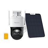
Since I moved into our new home this year, I have been making upgrades to turn it into the ultimate smart home. At the top of my to-do list is smart lighting, because it easily has the single biggest impact on comfort and how we experience our home.
Soon after setting up my Z-Wave and Zigbee networks, I got to work on smart lighting. And that’s where the newly launched Shelly Qubino Wave 1PM comes in. You can use these to turn your dumb switches into smart switches! Yes, this in-wall Z-Wave relay requires a neutral wire at the installation location. A no-neutral version is not available at the moment. The relay also supports power measurement and energy monitoring which is a great feature.
Because I already have physical dumb switches and many light fixtures that I like and have invested in, I do not want to replace them with smart bulbs. Instead I bought a variety of Shelly in-wall relays to install around my home. This includes three Wave 1PM relays – one for my foyer lights, and one in each bathroom. The Wave 1PM is the one that has virtually no reviews on the Internet, so let’s dive right in to see how well it has been working in my smart home!
A quick note: As an Amazon Associate I earn from qualifying purchases. This post contains affiliate link(s). An affiliate link means I may earn advertising or referral fees if you make a purchase through my link, at no extra cost to you.
How to use this Smart Relay
If I were starting all over again, I may consider going with smart switches but I have already invested in dumb switches and dumb ceiling lights that I do not want to replace. So it makes sense for me to retrofit my existing dumb switches to make them smart.
Installing a smart relay behind an existing switch or power socket in the wall is a good choice for when you want to keep your existing physical switch or socket but want to remotely control or measure an electrical load (light/fan etc.) connected to that switch.
This way you can control the connected load through the physical switch as well as remotely through the smart relay using Home Assistant or any other Z-Wave compatible smart home platform.
Since the Shelly Qubino Wave 1PM works as a Z-Wave repeater, I will be using it to strategically extend the wireless range of my Z-Wave network as well. Only mains powered Z-Wave devices are capable of being repeaters, so an in-wall relay is a great fit for this purpose.
For areas already having a strong Z-Wave signal, I prefer to use the much cheaper Shelly Wi-fi relays.
As the PM in the name suggests, this relay also supports power measurement. This is possible because it is not a dry contact relay – the relay is connected inline through the electrical load, so it is able to measure power consumption also.
If you want a dry contact type to control a traditional garage door for instance, go for the Shelly Qubino Wave 1 which does not have energy monitoring.
There is also a dual relay version called the Shelly Qubino Wave 2PM, which would be the Z-Wave equivalent of the Shelly 2.5. However this is quite difficult to find in stock at the moment.
Now here’s what I am going to use this smart relay for: I am going to install it in the wall behind the foyer light switch, and use it in an automation together with a Sonoff Zigbee motion sensor. The idea is that Home Assistant will turn on the lights through the relay whenever motion is detected and after some time switch them off. Of course if anyone wants to turn on the lights physically, the existing physical switch will continue to function exactly as it always has. But I also then have the added bonus of Home Assistant being aware fo the status of the switch and turn off the relay if someone forgets to turn the lights off! I can also use it as part of my night mode routine to ensure all lights are off at bedtime. The possibilities are endless!
Who’s Qubino?
Shelly has been making Wi-fi relays exclusively and they are the go-to option for most people. But Z-Wave and Zigbee devices have been sorely lacking in their product range. Now if you have been into home automation for quite some time, the name Qubino may ring a bell.
Qubino is a popular name in Europe where they are well known for Z-Wave devices such as dimmers & smart meters for a long time. So it makes sense that Shelly recently acquired Qubino instead of creating their own Z-Wave devices from scratch. In fact if you look closely, there are a lot of similarities between the new Shelly Qubino Wave 1PM / 2PM devices and the / 2 Relay.
I have to admit I have never looked at these Qubino offerings because they were pretty expensive. However the Shelly Wave 1PM/2PM devices are selling at just half the price.
What’s in the box
The Shelly Wave 1PM comes in a compact box as Shellys usually do. The box cover mentions the Z-Wave frequency (868.4 MHz) and Z-Wave Plus certification on the front.
The rest of the box states the specifications such as the Z-Wave 800 series chip and the EU declaration of conformity.
Inside the box, we find the Z-Wave relay, the DSK pin, and a user manual with a wiring diagram.
Specifications of the Shelly Qubino Wave 1PM
[table id=90 responsive=scroll /]
Design & Features – Taking a closer look
The Shelly Qubino Wave 1PM resembles previous Shelly relays and measures 37x42x16 mm (1.46×1.65×0.63 in). It should comfortably fit in most European standard wall boxes but do make sure before buying. I am disappointed that it is not as compact as the also new Shelly Plus 1PM Mini which is only 29x35x16mm / 1.11×1.35×0.63in.
The front of the cover shows the internal wiring logic between the terminals. There are also 2 tiny LEDs on the front of the relay – a blue LED and a green LED. These will blink in different ‘modes’ or patterns to indicate the status of the relay during inclusion, exclusion and the factory reset process.
The rear of the relay contains the Z-Wave action button that Shelly calls the S button. We also find a cutout in the case that gives access to the circuit board if needed. Of course unique to this Shelly relay is the external Z-Wave antenna to maximise wireless range.
Overall the relay seems to be well-built and of good quality.
So what are the features of this relay? On the Z-Wave side, the Wave 1PM supports the latest Z-Wave Series 800 standard. It also supports SmartStart although I haven’t tried that myself. I find the standard inclusion process simple enough. At the moment, the Wave 1PM is available only in the 868.42MHz frequency that is allowed only in regions such as EU/UK/Singapore. The relay supports S2 security, but I personally don’t see the need to use security for devices such as light switches. I do recommend it for external door locks though!
The relay supports both AC and DC wiring applications though I suspect the overwhelming majority of users will be using it in domestic AC wiring. It can handle up to 16A of AC switching current which is very good. The user manual mentions a maximum connected load of 3500 W, although I would be wary of running any relay at close to its maximum rating. What is important though is that you have that extra headroom which is a good margin of safety if you are switching something like 10A through this relay.
The Wave 1PM offers 3 modes of operation – as a toggle switch that changes on toggle (default), toggle switch that follows the physical switch, or as a momentary switch (push-button).
What is missing here is the ‘detached mode’ that lets you unlink the connected physical switch from the relay and use the switch as a virtual switch in Home Assistant. This means you can use smart LED bulbs (such as Ikea Tradfri) and stop people from cutting power to the bulbs through the physical switch. What would you do with the physical switch then? Of course use it to control the smart bulbs!
Installation & Wiring
The Wave 1PM user manual is quite detailed and shows the wiring diagram for using the relay in a 1-way switch scenario. This matched my use case, so installation was straight forward.
The terminal block of the Wave 1PM contains extra terminals for live and neutral connections. That makes it much easier to fit the relay into tight spaces without having to add extra Wago connectors.
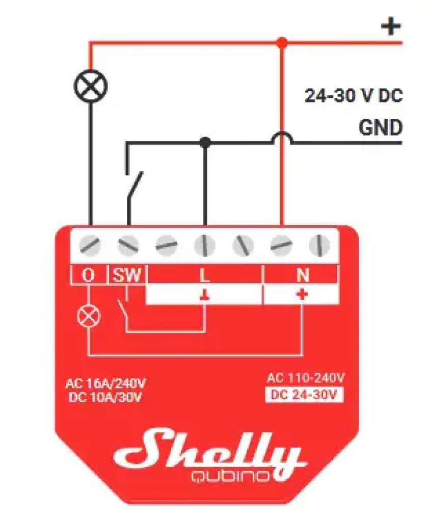
AC wiring diagramDC wiring diagram
I recommend getting a professional to do the wiring if you are not confident or are not allowed to by local regulations. I engaged a certified electrician to install the relay, this is the photo I took during the wiring:
2-way switch wiring before shortening ends, pushing fully into the terminals and tightening
You can see how the existing physical switch is connected to the SW and Live terminals.
Adding the Wave 1PM to my Home Assistant Z-Wave network
The best time to add the relay to a Z-Wave network is after wiring and before you put the relay into the wall. This is because there is a very helpful LED indicator on the relay that shows whether the relay is in pairing mode or not.
There are 3 ways to put the relay into pairing / inclusion mode:
Using the SmartStart feature
Using the S-button (only possible before the relay is closed up behind the switch)
Using the switch connected to the relay
I chose the S-button method because the electrician had not put the relay in and put the switch back yet.
As always, I recommend factory resetting the any Z-Wave device before including it in your Z-Wave network. In fact, this advice is given by most manufacturers as well (but not Shelly!)
So these are the steps I followed:
Wire the smart relay as per the wiring diagram
Make sure the blue LED is blinking in mode 1 (0.5 seconds ON, 2 seconds OFF)
Enable add/pairing/inclusion mode on your gateway (Z-Wave JS in my case)
Press and hold the S-button until the LED turns solid blue
Quickly release and then press and hold for more than 2 seconds the S-button until it starts rapidly blinking in Mode 3 (0.1 seconds ON, 0.1 seconds OFF)
Now the blue LED will be blinking a bit slower in mode 2 (0.5 seconds ON, 0.5 seconds OFF)
Wait for a bit and when pairing is successful, the connected load (a light in my case) will blink twice (1 sec ON > 1 sec OFF > 1 sec ON > 1 sec OFF)
The green LED will now blink in mode 1 (0.5 seconds ON, 2 seconds OFF)
Here’s the success message I received in Z-Wave JS:
I renamed the device from the Home Assistant devices page to ‘Foyer Lights’ because that’s what the relay controls.
Looking at the device page in Z-Wave JS, we can see the various sensors and controls exposed by the Wave 1PM:
The over-heat and over-current sensors were enabled by default but the Heat alarm sensor was disabled. So I went to the entities page in Home Assistant settings and enabled this.
These are the various configuration parameters available in Z-Wave JS for this device:
Performance
Now we get to the juicy part! So how does the Shelly Qubino Wave 1PM fare as a Z-Wave smart relay?
I like to look at the following areas when I judge a smart relay:
Local operation,
Responsiveness (both over the Z-Wave network and the physical switch),
Reliability,
Z-Wave range extension,
Safety and
Cost.
I use an RPi4 running ZwaveJS container with an Aeotec Z-Stick7 placed at the center of the house, and a NUC mini-pc in the garage running Home Assistant.
Local operation
The Shelly range of devices are well known for allowing fully local operation without any need for Internet access or cloud reliance. So that’s an easy one, full points here!
Responsiveness
So then let’s look at actually using the Wave 1PM. And right off the bat I ran into what is probably the biggest complaint I have about the Wave 1PM. There is a noticeable lag between the lights turning ON or OFF when the physical switch is used. Yes, the physical switch! I would put it at around 0.5 seconds. Not a deal-breaker, but disappointing. None of the other Shelly models I have around my home such as the Shelly 1PM or 2.5 have this lag.
Its almost as if the physical switch is in ‘detached mode’ (like the Wi-fi models can be put in) and there is some extra processing going on – but I have not set it up this way, in fact the Wave 1PM model doesn’t even support detached mode! That’s a downside by the way – you cannot wire up the switch, but detach the relay control from the physical switch via software and then use the physical switch as purely a virtual switch in Home Assistant.
All 3 relays I have of the same model exhibit the same behaviour. I even tried adding 1 relay in each Z_wave mode: no encryption, S0 encryption, and S2 encryption – nope it still lagged. I tried re-pairing, factory resetting, re-interviewing, everything. All the relays still lag when controlled by the physical switch.
Thankfully, there is virtually no lag when using Home Assistant to turn the relay ON or OFF. So my intended use case of motion detected foyer lights works well.
Reliability
How about reliability? I have been using the Wave 1PM in my foyer and 2 additional locations on a daily basis for over a month now. The relays have never gone offline, become unavailable, or failed to respond to commands from Home Assistant.
Wireless range is good, there are at least 2 solid concrete walls between my Aeotec Z-Stick 7 controller and the Shellys.
Power Measurement & Energy Monitoring
I was keen on using the power measurement feature and was satisfied with how it reports the power consumption as soon as the relay is turned on. There’s no delay at all unlike some smart power plugs I have used in the past.
The relay also supports energy monitoring, it creates a kWh sensor so that you can keep track of historical energy usage.
Repeater feature
Looking at my Z-Wave network map in Z-Wave JS, I could see that the various Wave 1PMs I installed were all connecting directly to the controller and exposed themselves as Z-Wave repeaters. So now I can add various battery powered Z-Wave devices in those areas without any range concerns.
Safety
The Wave 1PM meets all the safety requirements for such devices in the EU, however it is not UL certified for the USA.
Cost
When it comes to cost, the Wave 1PM costs twice as much as the regular Shelly 1PM in my EU country. Given that the regular Shelly 1PM has no lag in the lights turning on when using the physical switch, I would go for that model in the future.
The In-Wall Relay Competition
Some Z-Wave alternatives to the Shelly Qubino Wave 1PM are the Fibaro Z-Wave relay, the Aeotec Nano Switch relay, and of course the are still being sold, but all of these are more expensive than the Shelly.
Sonoff has Zigbee based relays that are cheaper than the Shelly Qubino Wave 1PM, so this may be an option if you are open to Zigbee. However I do have quality concerns when it comes to Sonoff devices that would go into my AC power wiring.
Aeotec has recently launched their Pico series of Zigbee relays that I have been trying out at home, this may be a great option when it comes to super-compact in-wall relays.
The VueVille Verdict
If you need a Z-Wave relay that can switch up to 16A, act as a router, has power measurement and don’t mind a 0.5 second delay when using the physical switch, the Shelly Qubino Wave 1PM is a good choice. The saving grace here is that there is no delay or lag when the relay is controlled over Z-Wave.
Product prices and availability are accurate as of the date/time indicated and are subject to change. Any price and availability information displayed on https://www.amazon.com/ at the time of purchase will apply to the purchase of this product.
Product prices and availability are accurate as of the date/time indicated and are subject to change. Any price and availability information displayed on https://www.amazon.com/ at the time of purchase will apply to the purchase of this product.
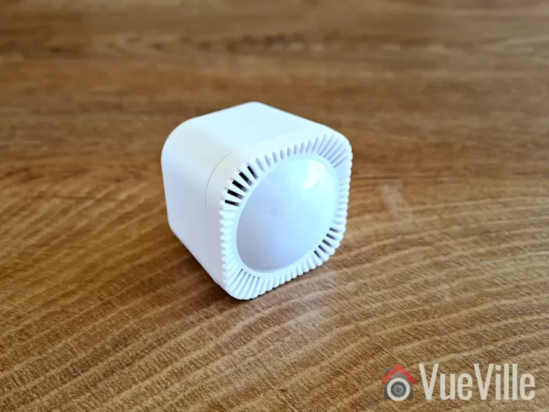
I recently installed Shelly smart relays in most of my light switches. So now I can control them from my phone through Home Assistant. But even better, I can now integrate my home lighting into my automations – such as linking lights in a room to occupancy.
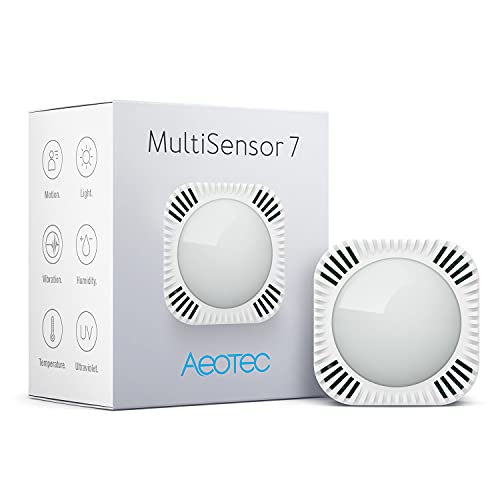
But to detect motion, you need a motion sensor. That’s where this small but very capable multisensor from Aeotec comes in. It’s called the Aeotec MultiSensor 7 and many thanks to Aeotec for providing this retail sample for our comprehensive review. As always, all opinions are our own.
A quick note: As an Amazon Associate I earn from qualifying purchases. This post contains affiliate link(s). An affiliate link means I may earn advertising or referral fees if you make a purchase through my link, at no extra cost to you.
Video Review
If you prefer a video instead, here’s a comprehensive video version of this review:
What’s in the box
The MultiSensor 7 comes with a short user guide, a USB cable, wall mounting kit and two CR123A batteries. In short, everything that you need to get you up and going.
Specifications of the MultiSensor 7
[table id=88 responsive=scroll /]
Design & Features – Taking a closer look
The MultiSensor 7 is a Z-Wave Series 700 device that supports the latest S2 security specification. It is the successor of the popular Z-Wave MultiSensor 6 that we reviewed a few years ago. That sensor was one of the very few that could act as a Z-Wave repeater when using USB power. I have one of those in a bedroom plugged into a USB charger for over 5 years now and it still works great.
In spite of the 7 in its name, the MultiSensor 7 has 6 sensors just like its predecessor: Motion, Tamper/Vibration, Temperature, Humidity, Light (Lux), & Ultraviolet Index. Where the MultiSensor 7 improves upon the 6 is in the 700 series Z-Wave support and better sensor sensitivity. For example the motion sensor now has a stated range of 10 metres (32 feet) vs. 5 metres (16 feet) earlier. The temperature and humidity measurement accuracy has also been improved.
Physically the MultiSensor 7 is similar to the 6. There is a bright multi-colour LED embedded on the front behind the translucent sensor cover. You can control the behaviour of the LED or switch it off entirely using the Z-Wave configuration page in Home Assitant (or using Z-Wave parameters in any other Z-Wave controller).
Popping the front cover off reveals the PCB with the motion sensor and other sensor instruments mounted on it.
The back of the sensor is exact the same as the Aeotec TriSensor which we have also reviewed. Just like the TriSensor, the Z-Wave action button is accessible only from the inside now (the MutiSensor 6 allowed you to press it from outside).
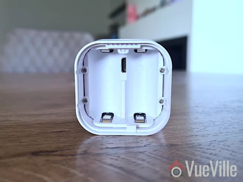
Slide open the locking mechanism and you get access to the batteries, the USB power port, and the reset button above it. The sensor is powered by two CR123A batteries that should last for 3 years according to Aeotec.
The MultiSensor 7 has IP20 certification but as the 0 in the IP20 suggests, it is an indoor sensor and does not have any protection against liquids. The 2 in IP20 means that it has protection against solid objects down to 12 mm (keeps fingers out). I wouldn’t recommend using it outdoors unless you plan to put it in a covered porch where it will not get wet or splashed.
Adding the MultiSensor 7 to the Z-Wave network
Now let’s look at adding the MultiSensor 7 to a Z-Wave network. I recommend doing this in the same room as your final installation location, but before permanently mounting it in case you want to fine-tune its position later. Why? Because if you pair it near the controller but then move it to the other end of your house, your sensor may not be able to reach the controller any more and it won’t know about any neighbouring routing devices! So the advantage of pairing it in the final location instead, is that your sensor will find the best possible route to the Z-Wave controller through neighbouring routing devices & remember this ensuring reliable operation.
You now need to choose whether you will use the batteries or the USB power route. Most people will probably use the battery option, but I tested the sensor in both battery and USB power mode. If you do change your mind after pairing the sensor in a particular power mode and want to switch to the other power mode, you should factory reset and re-pair it with your Z-Wave controller.
Jump to the Z-Wave setup chapter in our video review or continue reading after the video below:
Let’s put the batteries in. When you first power up the sensor, the LED will fade in and out with a blue colour. But it’s easy to miss this while inserting the batteries! Because technically the sensor can work with just 1 battery, so the moment you insert the first battery, the LED will fade in and out with a blue colour. Insert the second battery as well.
Finally, it’s time to pair the sensor with your Z-Wave controller. I use the Z-Wave JS add-on running on Home Assistant with an Aeotec Z-Stick 7. Put your Z-Wave hub into inclusion mode – this is how I do it in Z-Wave JS. I recommend including it with no security (so you don’t need to enter the DSK pin). Tap the action button on the MultiSensor. Just a short tap. It will light up a solid yellow as it enters pairing mode. It will then flash white/green for 2 seconds to indicate successful inclusion. Like so. But if it fails, it will be white/red instead and you should reset the sensor to factory conditions before trying again.
Wall mounting the MultiSensor 7
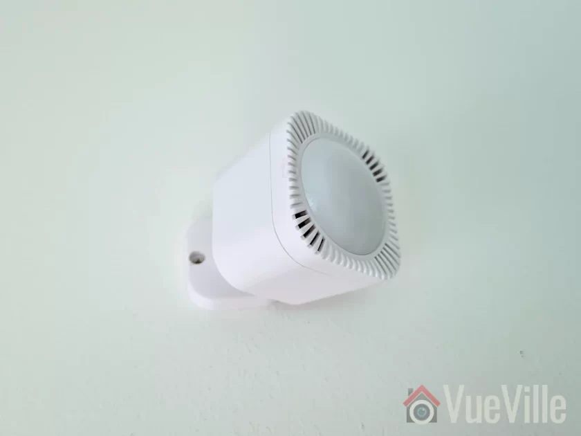
You could use the included 3M double-sided sticky tape to mount the sensor, but I prefer the more permanent screw method. Make sure you follow the advice in the user manual regarding location, height and motion sensor detection range.
To get the best results, avoid pointing the sensor at windows and take the time to think through all the possible ways people may enter and leave your intended detection area. This is crucial when using the motion sensor for presence detection and occupancy.
I chose this particular location for the sensor because then it can monitor the widest possible area including the entry from the corridor and the kitchen. The sensor has a 120 degree field of view which helps a lot as well.
Using the MultiSensor 7 in Home Assistant
Even though Z-Wave JS said the sensor was paired and added successfully to the Z-Wave network, I couldn’t find any of the sensor entities under my entities list. No worries though, this happens sometimes when adding battery-powered sensors. I simply used the Re-interview node command with the reset security classes box ticked to force Z-Wave JS to identify the MultiSensor’s capabilities.
This worked and I could then view readings for all of the MultiSensor’s 6 sensors. All the configuration parameters also showed up. However, unlike the MultiSensor 6 there was no obvious vibration sensor entity. The vibration sensors are linked to the entities alarmLevel and alarmType which were disabled by default, so I had to enable in the Home Assistant entities list.
Its important to understand that the vibration sensor in this multi-sensor also serves the function of tamper detection. Unfortunately the sensor uses a notification event rather than a binary sensor for vibration detection. You can see this in the logbook section in the screenshot above, as well as in the Z-Wave JS debug log as seen below. There was no option to change the reporting type in the Z-Wave configuration parameters (some devices do allow you to do that, but this sensor doesn’t).
But we can work with that. First I created an input boolean helper to act as the vibration sensor:
Then I created the automation below to detect the Z-Wave CC notification event and then use that to toggle my helper on and after a minute off. This simulates a vibration sensor perfectly. You can adjust the duration to simulate a cool-down period.
Test system: Raspberry Pi4 (8GB RAM) running DietPi and Home Assistant Supervised in a Docker container, Aeotec Z-stick Gen 7 USB dongle for Z-Wave, Z-Wave JS as controller software (HA add-on).
Battery-power mode
I was keen to put the claimed 10 metres (33 feet) range of the MultiSensor to the test. The longest room in my house is the living room and I was able to position the sensor such that its maximum possible detection distance to the corridor wall came to 10 metres. Perfect! So that’s where I did this test. To make it even more of a challenge the entry point would not be head-on but off to the side of the sensor. This is as close to real-life as a test can get!
And the results are impressive! I measured the distance between the sensor and the point at which it detected motion (green flash) at just under 10 metres which is also the claimed figure for the motion sensor. It takes around a seconf from the sensor detecting motion (green LED flash) to the Shelly 2.5 relay turning the lights on. So overall a very good result.
Moving to the temperature and humidity sensors, the readings are similar to those of the Mi Air purifier in the same room. Any discrepancy can be put down to them being at opposite ends of the room, and the 3 metres of height difference with the air purifier on the ground and the sensor being nearer to the ceiling.
While motion sensor reports are of course instantaneous, the default reporting interval for the other sensors is 240 seconds. You can reduce this to 60 seconds on battery power or down to 1 second on USB power.
You may be wondering about the wireless range of this sensor. Looking at the Z-Wave JS network map, I can see that the MultiSensor 7 found a route to the controller through the Aeotec Doorbell in the foyer around 10 metres and 2 concrete walls away. Makes sense and that’s what I would expect it to do. If you power it up over USB before pairing, the MultiSensor will be a routing device. If you have AC/USB power at your installation point, I’d recommend that.
I used the sensor for over a month and the battery remains at 100%. The previous MultiSensor 6 had excellent battery life with the batteries lasting well over 2 years and I expect this new model to be similar. But time will tell whether it will last the 3 years that Aeotec states on the engineering datasheet.
Compared to the MultiSensor 6, the MultiSensor 7 truly has twice the motion detection range (10 metres vs. 5 metres), improved wireless range and the option of S2 security should you need it.
USB Power Mode
I repeated the tests above with the MultiSensor 7 on USB power mode and the results were similar. If anything, the responsiveness of the sensor seemed to get even better with virtually zero lag or delay between motion detection and automations firing. Not that it was bad on battery-power, it went from <0.5 seconds to almost instantaneous. I also set the auto-report interval to 60 seconds for more periodic reporting from the various sensors, this is very useful for lux level based lighting automations.
MultiSensor 7 vs. MultiSensor 6
So to summarise, the major differences I came across with the 7 vs. 6 are:
Z-Wave 700 support on the 7 vs. 500 on the 6
S2 security (although I dont recommend using Z-Wave security for sensors, its more relevant for door locks)
10 metres motion detection range on the 7 vs. 5 metres on the 6
Better temperature and humidity measurement accuracy on the 7
Improved wireless range (although I couldn’t test that as I have a solid mesh with many Z-Wave router devices nearby)
The VueVille Verdict
So what’s great about the MultiSensor 7? You get 6 of the most useful sensors for just about any home automation scenario in one compact package. The most important sensors such as motion, temperature and humidity work very well. The motion sensor especially is very sensitive and can truly detect people at a distance of 10 metres, which is stunningly good. Temperature, humidity, light level, and UV reporting intervals can be changed from the default 240 seconds, and can go down to 60 seconds on battery power and 1 second on USB power. And it can act as a routing device on USB power. You get the USB cable and a wall mount, no need to buy that separately! So overall this MultiSensor is very good value if you need all these different sensors.
While I didn’t find any issues with this MultiSensor itself, the Z-Wave technology itself does seem to be going the way of Betamax with Zigbee being VHS in this analogy. Yes Z-Wave devices are more reliable and do not suffer from interference with Wi-Fi networks like Zigbee does. But the gap is closing – I have set up a very stable Zigbee network at home without much effort using the tried and tested Sonoff Zigbee Dongle (ZBDongle-P). The biggest reason for Zigbee devices popularity IMO is that they are much cheaper because of the less strict certification process for device manufacturers.
This also means there’s far more choice in the market for consumers with familiar names such as Ikea joining the action. I expect a Zigbee equivalent to the MultiSensor 7 to emerge in the near future. But for now, the unique combination of 6 useful sensors and the USB power option make the Aeotec MultiSensor 7 a compelling choice.
So what do you think about the MultiSensor 7? Leave your comments or any questions you may have below!
Product prices and availability are accurate as of the date/time indicated and are subject to change. Any price and availability information displayed on https://www.amazon.com/ at the time of purchase will apply to the purchase of this product.
Ever since I started setting up the VueVille DIY Smart Home, I have been focused on Z-Wave. Back in 2017 when I was starting out, Z-Wave was the only reliable DIY option for smart home enthusiasts who didn’t want to rely solely on Wi-Fi.
Zigbee was beginning to make a mark but lax compliance with the standard meant that you couldn’t count on Zigbee devices to work well together. But things are very different now and that’s what made me revisit my decision now. Zigbee has come a long way and after just 1 month of exploring the Zigbee ecosystem, I can confidently say that its worth considering for us Z-Wave holdouts. Not as a Z-Wave replacement, but rather to complement it. More on that later.
The first bit of kit that I purchased is the product I am reviewing today: a Zigbee USB stick called the SONOFF ZigBee 3.0 USB Dongle Plus (model ZBDongle-P). Its essentially similar to a controller in the Z-Wave world, but in the Zigbee world a controller is called a coordinator. This particular model comes pre-flashed with the Zigbee coordinator software so is plug and play with Home Assistant ZHA and Z2MQTT.
Please note that there is another model called the ZBDongle-E, but this uses a newer less supported chip and currently is not recommended for use with my preferred Zigbee integration in Home Assistant: Zigbee2MQTT.
A quick note: As an Amazon Associate I earn from qualifying purchases. This post contains affiliate link(s). An affiliate link means I may earn advertising or referral fees if you make a purchase through my link, at no extra cost to you.
Zigbee Basics
If you’re new to the world of Zigbee like I am, here’s a primer on what you need to know.
Just like Z-Wave, Zigbee is also a mesh wireless protocol. This is one of the best things about Z-Wave that allowed me to create a strong reliable mesh network among all my Z-Wave devices. This is not possible with Wi-Fi or Ethernet where each device requires a direct connection to the router (although multiple WAPs can somewhat alleviate this).
So what does this mean in practice? Suppose your Zigbee coordinator sits in the garage with the rest of your tech gear, like mine is. And at the other end of your home, you want to place a temperature and humidity sensor like the Sonoff SNZB-02.
With Wi-Fi, you would need to be within range of your Wi-Fi router or have a WAP nearby. With Zigbee again the ideal scenario is if the sensor can connect directly to the Zigbee coordinator. But if its not, the mesh network comes into play. Most mains powered Zigbee devices such as smart bulbs or smart relays are able to act as ‘routers’ by relaying signals between the coordinator and other Zigbee devices. Do note that being mains powered does not automatically make a Zigbee device a router!
So our battery powered sensor can connect to the nearest Zigbee router and thus communicate with the coordinator. Thus our sensor here is an ‘end device’. Such battery powered Zigbee devices are usually not able to act as routers.
Now the biggest downside of Zigbee is that it uses the same frequency as 2.4 GHz Wi-Fi. This creates the potential for interference between your 2.4GHz band Wi-Fi network and your Zigbee network. I have learnt after much research (Metageek is an awesome resource) and quite a bit of fiddling that the best way to ensure your Zigbee and WiFi networks can coexist is by ensuring the specific frequencies (i.e. channels) they use do not overlap.
One thing to watch out is that the ‘channel’ numbering that WiFi and Zigbee use are similar and so you may think the frequencies won’t overlap. But they do! For example it may seem that Zigbee channel 11 uses the same frequency as Wi-Fi channel 11, but they don’t! In fact, Zigbee channel 11 overlaps Wi-Fi channel 1. The Metageek resource linked above explains it very well.
So my suggestion is:
Put your WiFi access points on channel 1 (if you have more than one WAP, use 6 for the one that’s furthest from the Zigbee coordinator and 1 for the WAP that’s closest to the Zigbee coordinator).
Put your Zigbee coordinator on channel 25 (or 20 if you are in the US).
This configuration ensures minimal overlap between your Wi-Fi network and the Zigbee network.
What’s in the box
The Sonoff Zigbee USB stick’s retail package is very compact and has an unusual blue color. Unusual for Sonoff with their trademark orange branding you’d find for Zigbee gear.
Inside the box we find the following:
ZBDongle-P USB coordinator
Antenna that you can screw on
User manual
Specifications
[table id=87 responsive=scroll /]
Taking a closer look at the Sonoff Zigbee Dongle
The Sonoff ZBDongle-P has a metallic body and feels reassuringly solid in the hand. The front design looks a bit like a heat sink, which is a smart thing to do with a metal enclosure. You just need to screw on the included antenna and the dongle is ready for use.
The ZBDongle-P uses a CC2652P based System on a Chip (SoC) design. The P in the CC2652P model number refers to the power amplifier this chip has onboard. It allows up to a 20dB signal output power but the outdated default firmware Sonoff has pre-flashed this dongle with seems to support only 5dBm. This can be rectified by flashing a newer firmware (which I detail below) and can be easily adjusted in Zigbee2MQTT.
The USB-serial interface is handled by the CP2102(N) chip.
The backside sports the model name, safety and regulatory information.
The USB-A port should be plugged only into a shielded extension cable on a USB 2.0 port. USB 3.0 ports can cause interference with Zigbee networks, and is probably the root cause of many complaints about poor reliability when using Zigbee USB dongles.
Setting up the Sonoff Zigbee Dongle
With Home Assistant, there are 2 integrations you can choose to build your Zigbee network around: the official ZHA integration and the community effort called Zigbee2MQTT. I recommend Zigbee2MQTT because it has slightly wider device support and is generally quicker to add support for new devices as well.
I run Home Assistant on a Raspberry Pi4 (running DietPi Linux distro) with an SSD connected via USB 3.0. I also have the Aeotec Z-Stick 7 plugged into a USB 2.0 port. Everything works well without the need of a USB powered hub. That left me with 2 free ports on the Pi – 1 USB 2.0 and 1 USB 3.0.
So I happily proceeded to plug the Sonoff dongle into an extension cable off the free USB 2.0 port. My troubles began here because I foolishly assumed that just because Linux could see the device plugged into a USB port would mean that Home Assistant would also be fine with it. Big mistake. I spent a couple of hours checking everything until I realised the Sonoff dongle is probably not getting enough power from the Pi’s USB bus. So I moved the Sonoff to an externally powered USB hub and BOOM, Home Assistant immediately recognised the Sonoff!
So here is a summary of the steps I followed to set up the Sonoff dongle:
Plug in the device into your Home Assistant. Make sure you use a USB 2.0 port and a good quality extension cable. USB 3.0 ports cause interference and an extension cable minimises interference as well.
Home Assistant’s built-in Zigbee integration called ZHA will recognise the Sonoff and offer to set up the integration – click Ignore to cancel the ZHA setup.
Install the ‘MQTT Broker’ addon
Install the ‘Zigbee2MQTT’ addon
Create a Home Assistant user for Z2M to use to connect to the MQTT broker
Configure Z2M with: 5.1 the user and password details you created above 5.2 Find the USB port ID using this command in a terminal window dmesg | grey tty
Go to Addons -> click Enable watchdog for MQTTbroker and start it
Go to Devices & Services -> Click configure on MQTT, click Submit and again click Submit & finally click Finish.
Go to Addons – > click Enable watchdog for MQTTbroker and start it
Click Zigbee2MQTT on the sidebar, and change the Zigbee channel to 25 in settings (20 if you are in the US as channel 25 has a lower maximum power limit by law).
IMPORTANT: Do this before pairing devices! If you try to change the Zigbee channel later, you will have to repair all your devices!
Add your first device: In Zigbee2MQTT, click permit join at the top and follow the device instructions to join a Zigbee network
I found that my Sonoff dongle came flashed with the ZStack firmware version 20210708. I first tested the dongle with this default firmware and then tried the latest 20230507 version as well. More on that later.
Zigbee Pairing with Zigbee2MQTT & Wireless Range
I purchased a variety of Zigbee devices and was able to pair all of them without any issues whatsoever:
Sonoff Power Plug
IKEA Vindstyrka
Sonoff Motion Sensor,
Sonoff Temperature and Humidity Sensor, and
Sonoff Door/Window Contact Sensor
The best practice when starting a new Zigbee network is to pair the wired mains-powered devices first. This will create a strong mesh network that the battery powered devices can then be added to.
So I first paired the Sonoff power plug and then the IKEA Vindstyrka. Both devices were paired easily and without any fuss. They were both detected as router devices, thus creating and extending the Zigbee mesh network. All the sensors were detected automatically and Home Assistant created the device entities correctly.
On to the battery powered devices now. Here, there were two things I wanted to test.
Adding battery-powered Sonoff devices directly to the coordinator – I did this for sensors that were at most 10 metres away with 1 or 2 concrete walls in between.
Adding battery-powered Sonoff devices through the router devices – I chose this option for those devices that were at the other end of the home and had 3-4 concrete walls in between.
I added over 6 Sonoff sensors in all, in their final installation locations and every time it was smooth sailing. No pairing errors, and I;ve not experienced any sensor dropping off the Zigbee network.
Here’s a network map produced by Zigbee2MQTT that shows the link quality and the routes between each device:
My Zigbee Network Map in Zigbee2MQTT – click to enlarge
A few things struck me as very odd when I first saw this network map and the link quality information. The Sonoff Smart Plug (powering the garage door opener) is located in the garage along with the Sonoff Zigbee co-ordinator, whereas the Ikea Vindstryka is at the other end of the house with 3 concrete walls in between. But the Ikea link quality is way better at 96 compared to the 72 of the Sonoff Smart Plug.
The other thing worth noting is that the Garage-Laundry door sensor is a Sonoff Door/Window sensor also placed in the same garage right next to the Zigbee dongle. But with the ‘permit join all’ option in Zigbee2MQTT, it chose to connect through the Sonoff Smart Plug instead of directly to the Zigbee co-ordinator. I wonder why that is. Also, the link quality is only 29 from the Sonoff Smart Plug to the Sonoff Door sensor even though they are in the same room! Interestingly, a similar door sensor from Sonoff placed in the same room as the Ikea Vindstryka has a far better link quality of 159. My conclusion here is that the Ikea Vindstryka is a superior router device. So I won’t be buying any more Sonoff smart plugs with the intention of using them as a router – they are clearly not very good at this.
Updating the firmware
I was wondering whether the 2+ year old Z-Stack 20210708 firmware version on the device was the culprit. This fimrware had a +5dB limit on the antenna gain instead of the +20dB the hardware is capable of.
So I flashed the latest 20230507 firmware using the excellent instructions on post #2 of this HA community forum thread. This firmware has a default antenna gain of +9dB and further allows it to be raised all the way to +20dB if needed. I didn’t have to repair my devices which was great, and here’s the new network map:
Zigbee Network Map on firmware 20230507
The most striking difference is that the co-ordinator now had much higher link quality to both the router devices. For example the linkquality for the co-ordinator and Ikea pair went from 96/29 to 132/46. If you are not familiar with this figure, linkqualiy for a router is always expressed two figures separated by a slash. The first figure is the strength of the link as seen by the co-ordinator and the other is that as seen by the router device.
Some other devices saw improvements as well, whereas a Sonoff door sensor got worse. The link quality reporting overall still seems a bit off to me.
Overall I was quite happy with the firmware upgrade. I have a feeling as the Zigbee mesh adjusts to the new firmware, the link quality may improve further.
What I didn’t like about the ZBDongle-P
While all my devices worked as expected and I didn’t experience any devices dropping off the Zigbee network, I couldn’t help but wonder about the link quality reporting of the dongle. The dongle seems to be reporting much lower values than even the Ikea which is just a router device.
Now it could all simply be down to the way the dongle calculates link quality is not a 100% correct. Indeed, this Home Assistant community forum thread seems to be suggesting so.
Still, this does make me wary of relying on the reported link quality numbers to design my Zigbee network.
Verdict
[review]
The ZBDongle-P is a tried and tested Zigbee co-ordinator and is on the list of recommended USB dongles for Zigbee2MQTT. It also works well with Home Assistant’s built-in Zigbee integration called ZHA.
If you are keen on Zigbee2MQTT, the ZBDongle-P is the better choice as the ZBDongle-E is not yet fully supported in that integration. However if you prefer ZHA, both are good options.
I found the ZBDongle-P to be an easy to setup and easy to use USB adaptor with good wireless range. The only major hiccup I had was my Pi4 not supplying enough power to the dongle but this was resolved by using a powered USB 2.0 hub. After that, I was able to pair all the devices I tried without any fuss and I have a solid Zigbee network in my home as a result. Upgrading the firmware brought a welcome improvement in mesh quality and I highly recommend this step if your device comes with an outdated version as mine did.
Product prices and availability are accurate as of the date/time indicated and are subject to change. Any price and availability information displayed on https://www.amazon.com/ at the time of purchase will apply to the purchase of this product.
A few months ago, I reviewed my first 8 Megapixel IP camera from Reolink, the RLC-824A. Reolink has continued to put out very unique cameras and I have one such device for review today: the fully wire-free PTZ called Reolink Trackmix Wi-Fi (Battery) with dual-lens auto-tracking.
Reolink kindly provided a review sample of this Trackmix which has a built-in battery and the Reolink Solar Panel 2, which together make this camera 100% wire-free and self-powered! As always, we are going to look at the features, setting up the camera, battery performance, motion detection performance, video & audio quality and how it works with our VueVille DIY Home CCTV system and our DIY Smart Home Automation System!
NOTE: Reolink also has a version of the Trackmix Wi-Fi that is mains powered (instead of a battery), it has a 4K sensor and RTSP support.
A quick note: As an Amazon Associate I earn from qualifying purchases. This post contains affiliate link(s). An affiliate link means I may earn advertising or referral fees if you make a purchase through my link, at no extra cost to you.
Video Review
If you’d prefer this post in video format, here’s an in-depth video review:
How to use this camera
The TrackMix Wi-Fi can work as a standalone security camera using its built-in microSD card, or you can connect it to a Reolink NVR. Please note that older NVRs may not support the dual-view feature.
Like most battery powered cameras, the TrackMix WiFi does not support RTSP or ONVIF and so cannot be added to Home Assistant or similar home automation software.
It does however support Alexa and Google Home, neither of which I use in our fully-local self-hosted smart home.
What’s in the box
Box contents list of the Reolink Trackmix:
Reolink TrackMix Wire-free IP camera
USB 2.0 to USB-C cable
Screws, rawl plugs
Installation and operation guide with photos
Mounting hole template
Surveillance sign
UK and EU regulatory compliance certificates
Box contents list of the Reolink Solar Panel:
Reolink Solar Panel 2
USB-C male-to-female conversion cable
Mounting arm
Metal backing plate
Screws, rawl plugs
Installation and operation guide with photos
Mounting hole template
Mounting strap for tree or pole
UK and EU regulatory compliance certificates
Specifications
[table id=85 responsive=scroll /]
[table id=86 responsive=scroll /]
Design & Features
The TrackMix comes in the traditional form factor of a Wi-Fi PTZ camera. No surprises there. But Reolink has opted for a mix of metal and plastic for its construction. This is a departure from other cameras we have reviewed in the past which were fully metallic. However the camera doesn’t seem to be negatively affected by this.
I was a big fan of the RLC-423 PTZ that Reolink brought out a long time ago. While that was a single-lens model, the TrackMix has a dual-lens setup. That’s the USP of this particular PTZ camera together with auto-tracking.
The Dual-View lens gives it the ability to produce 2 different video streams simultaneously: a panoramic view from its wide-angle lens, and a separate auto-tracking zoomed-in view from the close-up lens. This clever setup overcomes the biggest flaw of traditional PTZ cameras – when a single-lens PTZ is auto-tracking by zooming into a target object, it is blind to everything else going on in the scene. This can lead to a costly mistake if valuable evidence of a crime is going on outside the zoomed-in camera’s view!
The front of the camera also houses the 2 EXIR LEDs, the floodlight LED, day-light sensor, microphone and the PIR sensor for true motion detection. Uniquely, the TrackMix has not only Infrared LEDs for night vision, but also a bright LED floodlight for colour night vision. I found the LED to be bright enough for identifying faces up to a fair distance but of course for a larger yard or area you would need additional lighting. The Reolink Floodlight is a great option here as it can turn on when any linked Reolink camera detects motion.
I was quite intrigued to find the PIR sensor here and how it integrates together with the smart motion detection. So I have included a section later on how it all works together. The PIR sensor doesn’t have a claimed range but I would expect the standard 5 metres that similar cameras claim.
The rear of the camera has the speaker for 2-way audio, the same speaker is used for the siren deterrent feature.
We find the microSD card slot at the bottom of the camera. It can take cards up to 256 GB which is more than sufficient.
But what about the reset button? Where is that hidden? Reolink always finds a smart place to put it.
Move one of the antennas down on one side and you will find an unnamed panel held with screws. Remove those screws and you find not only the reset button but an ON-OFF switch as well. Now that’s a great addition!
Finally the single USB-C cable comes out through the top of the housing and through the wall mount. This cable can be used to charge the built-in battery either from AC power or the Reolink Solar Panel 2.
Installation & Setup
Charging the battery: Following the user manual, I plugged the camera into my mobile phone charger using the camera’s USB-C cable. After a short while, the indicator light on the cable turned green and we were ready for the rest of the setup process.
Hardware setup
Installing the camera and solar panel physically on to my test rig took just under 10 minutes, all the required rawl plugs and screws are provided. I also added a microSD card.
I plugged in the TrackMix camera’s USB-C cable (female end) into the Solar Panel’s USB-C cable (male end). Finally I turned on the camera using the aforementioned power switch.
With previous camera reviews, I had to spend quite a bit of time planning out how to power the camera and running a PoE Ethernet cable to it. But the Reolink Solar Panel made all of that redundant, and the camera being Wi-Fi meant that there were zero cables to route, install or bury!
I couldn’t find a web admin interface at the camera’s IP address, so decided to follow the default setup method which is the Reolink mobile app.
Mobile App Setup
Reolink cameras are usually a breeze to set up because of a few reasons:
Reolink sets the cameras to use DHCP by default.
Reolink cameras do not require an Internet connection for initial setup.
I did notice one odd thing about the Reolink TrackMix though – the setup process could be completed only if my phone running the Reolink app was also in the same VLAN as the TrackMix. I have never encountered this behaviour with Reolink cameras before, but have seen it with my Mi Smart Air Purifier and Mi Smart Humidifier.
Since the TrackMix Wi-Fi camera does not have an Ethernet port, the only way you can set it up is using the mobile app and the voice guidance of the camera.
When I turned on the TrackMix, the voice guided setup started by asking me to install the mobile app and scan the QR code on the top of the camera.
Step 1: I opened the Reolink Mobile app and tapped the + button at the top right to add a new camera
Step 2: I then scanned the QR code on the top of the camera, which allowed the mobile app to read the UID of the camera (printed on the top of the camera).
Adding the TrackMix to the Reolink app
Step 3: The app then asked for the Wi-Fi network details which I entered, and it generated a large QR code. It did ask for location access, I selected ‘approximate location’ and I allowed it only this once. I selected the 5 GHz network for the maximum wireless speed. If your camera is far away from the access point, you may need to choose 2.4 GHz instead.
Step 4: The camera prompted me to let it scan the QR code from the mobile screen, and then beeped as it connected successfully to the Wi-Fi network.
Step 5: The mobile app then prompted me to set up a device password for the default admin account, name the camera, and finally loaded the dual livestream view from the Trackmix.
Step 6: I formatted the microSD card which had some data on it from a previous Reolink camera.
So overall it was a painless process, but I did not appreciate the fact that it would only work if the mobile was in the same VLAN network as the camera.
Features
I will focus on the Reolink mobile app and the TrackMix’s unique features in this section: the Dual View lens, LED floodlights, Siren, Solar panel, battery life, PIR motion detection, smart person/vehicle/pet detection, and the auto-tracking of targets.
Out of the box, these are the default settings on the Trackmix Wi-Fi camera:
Smart Detection: ON with sensitivity of all 3 types (Person, Vehicle, Pet) set to 60.
PIR Motion Sensor: ON with sensitivity set to 80.
Camera Recording (to microSD card): ON, with post-motion recording of 8 seconds
Clip overwrite: ON
Push notifications: OFF
Email Alerts: ON
Siren: OFF
Audio recording: ON
Infrared Lights: Auto
LED Spotlight: Auto (spotlight turns on when alarm event is detected giving colour night vision)
Auto-tracking: OFF
Status LED (blue): ON
Please watch the video review for a full tour of the Reolink mobile app and the various settings available.
Viewing the Dual lens simultaneously
While live-viewing through the mobile app, you are presented with both views simultaneously on the screen. The same layout is used while reviewing recorded clips as well.
So opening up the Reolink mobile app shows the cameras connected to it, including the TrackMix. Sadly the preview doesn’t update automatically, you need to tap it and open it to see the live stream.
Dual lens live-stream
Since this is a PTZ, lets look at that first. Panning is easy and responsive. You can adjust the zoom level of the close-up lens, and the speed of the panning.
I like to keep the camera zoomed in to the doorway by default, and the monitor point setting lets me do that. You can also set up preset areas of the scene that you can quickly jump to. But I think there’s a bug in that the camera doesn’t store the zoom level when you create a preset point, it seems to just store the X & Y coordinates. So you will have to zoom manually each time.
You can also view the dual lens streams using the Reolink Desktop app, more on that in the performance testing section later.
LED floodlights & Siren
Bright and powerful LED Floodlight
Uniquely, the TrackMix has not only Infrared LEDs for night vision, but also a bright LED floodlight for colour night vision. I found the LED to be bright enough for identifying faces up to a fair distance but of course for a larger yard or area you would need additional lighting. The Reolink Floodlight is a great option here as it can turn on when any linked Reolink camera detects motion.
The built-in siren is also a great feature for scaring away intruders when motion is detected, or on demand through the mobile app. Its just loud enough to scare away intruders but not deafening.
2-Way Audio
Suppose you check in on your PTZ and see an unsavoury character loitering about. Just hit the Siren button to scare them away. What if you want to give them a few choice words too? Just hit the Talk button and then tap to talk. Now you have 2-way audio to your camera from anywhere in the world. I found that the audio quality was good enough to have a conversation if you need to!
Reolink Solar Panel 2
The Reolink Solar Panel 2 is the latest revised version that improves on the original significantly. It has a maximum output power of 5.8 W and is weatherproof with an IP65 rating.
Smart motion detection
The burning question on my mind was how exactly the TrackMix uses both the physical PIR motion sensor and the traditional software-based smart motion detection. By default, both methods are turned ON in the camera settings.
I could not find any explanation of how these features work together in the user manual or on Reolink’s website. But from my testing detailed a bit later, I gathered that the two features work well together even in totally dark situations.
In the app, there are 3 settings which when combined are very helpful for reducing false alerts.
You can set the detection zones for each type separately – person, pet, vehicle and others.
You can also adjust the sensitivity of each detection type.
Finally, and most importantly you can define the minimum and maximum object sizes that will trigger an alert for each smart detection type.
By default Auto tracking is OFF, I would keep it ON actually and its nice that you can set it to track just persons and vehicles but not pets for example. You can further finetune the tracking logic if needed and even set a schedule when tracking should be ON (say only when you are at work and in the night – so that it doesn’t keep tracking your kids playing in the yard).
You can schedule SD card recording and adjust the post-motion record duration. The camera does support pre-motion recording but curiously doesn’t let us adjust it. From looking at the clips it seems to be around 8 seconds as well.
Auto-tracking
This is a very useful feature in a PTZ camera and at this price point definitely an expected one. The camera lens is able to perform Dual-Tracking as Reolink calls it. This means that in the panoramic view, the camera aims to keep the detected object in its sights. In the zoomed-in view, the camera zooms into the targeted object and aims to follow it closely.
Performance Testing Results
Technical settings:
For testing the camera, I turned ON physical auto-tracking (the default is digital tracking only). PIR and smart detection were ON by default. So in short, all the motion detection features of the camera were turned on.
The quality settings were left at their default 4MP @ 15 fps with 3Mbps bitrate.
Video quality & Motion detection
Daytime test
In my daytime video test at a distance of 5 metres (the maximum possible in the balcony of my temporary rental), the PIR of the camera picked up on the motion instantaneously and started tracking the test subject. The wide-angle lens captured the entire scene whereas the telephoto lens zoomed in to keep the subject dead center of the view. The image was sharp and detailed as expected, and audio was also of good quality.
Night-time test
As dusk fell, I repeated the test. As soon as the PIR sensor detected motion, the camera switched from the Infrared LEDs to the spotlight LEDs thus adding colour to the scene. Even in the darkness, the camera had no trouble tracking the test subject throughout the entire test duration. It did a great job preserving detail that would be useful for facial recognition, and the image was not washed out at all. There was also no ghosting or tearing. Well done TrackMix!
Push Notifications
I always put my security cameras in their own dedicated VLAN which doesn’t have Internet access. This means the camera’s push notifications will not work – this depends on Reolink’s P2P servers. This is not an issue for me because I use Home Assistant for actionable notifications (previously HomeSeer).
But for the purposes of this review, I gave the camera Internet access and push notifications started working. As always notifications arrived promptly and reliable. The only strange thing I noticed is that tapping a notification takes you to the live view stream and not the recorded clip. This makes sense if you tap the notification while the alarm event is still underway, but doesn’t help if you are catching up on your notifications and would like to be taken straight to the clip of the alarm event. Maybe Reolink could use some conditional logic here to achieve this?
Reviewing recorded clips
Lets look at the playback feature where the camera uses its built-in NVR ability. Clicking on the playback button takes you quickly to the timeline where each motion detection clip is shown along with the type of motion detected. This is a great feature and helps to quickly scan for just the types you are interested in, such as persons or vehicles.
Playback in the Reolink mobile app
You can also drag the timeline selector to a specific point and just see the clips recorded at that time. Both the wide angle lens and telephoto zoom lens clips are played simultaneously so you can see the entire scene at all times. I observed no delays whatsoever during playback – and that’s partly also due to the great Wi-Fi I have using Unifi gear.
Battery Life
Battery life has been excellent all through the 3 months I have been using the camera, which included late winter and spring. The lowest I ever saw the battery at was 98% and that too after a few cloudy days with hardly any sunlight. Otherwise the Reolink Solar Panel 2 always kept the battery topped up at a superb 100%.
One comment I have is that with the camera cut off from the Internet (as the VLAN the camera is in has no Internet access), the detailed battery monitoring page of the mobile app always failed to load. Of course I could always see the battery charge level % in the home screen of the app. But restoring Internet access made the detailed battery section work again. I found this quite strange, but didn’t affect the operation of the camera in any way.
Reolink Desktop App
Reolink Desktop Client
I was able to add the TrackMix WiFi to the Reolink Desktop app but only if the camera had Internet access. The client could not even detect the camera without the camera having Internet access. This was not very encouraging. So I cut off the Internet access and returned to the mobile app which still works without Internet access.
Compatibility with Home Assistant
Unsurprisingly the Wi-Fi version of the TrackMix under review here today is not supported in the Home Assistant Reolink integration. Battery powered cameras are generally not supported anyway, and the TrackMix also doesn’t provide an RTSP stream. However the mains-powered WiFi and PoE versions are supported by the Reolink integration.
Considering how strong the battery life is and the fact that the Solar Panel 2 can easily keep the TrackMix Wi-Fi permanently powered, I would hope the TrackMix Wi-Fi battery version would also be supported in the future.
Reolink Solar Panel 2
The Reolink Solar Panel 2 is the latest revised version that improves on the original significantly. It has a maximum output power of 5.8 W and is weatherproof with an IP65 rating. As we saw earlier, it keeps the battery topped up comfortably at 98-100% and that’s not even in a location where the camera gets all the sunlight available to it. Very impressive.
The first version of the solar panel only an output power of 3W.
Frequently Asked Questions (FAQ)
Can I adjust the zoom level of the zoomed-in lens view?
Yes, through the PTZ section of the mobile app. Tap the Zoom button to adjust the zoom level.
Verdict
The Reolink TrackMix is a very good Wi-Fi PTZ with auto-tracking and smart motion detection. The dual lens feature is the biggest differentiator here. Together with the superb Reolink Solar Panel 2, the TrackMix is a great 100% wire-free choice for areas where you can’t run mains power or Ethernet to.
But since this is a battery powered Wi-Fi camera, the obvious downside is the lack of ONVIF, RTSP or an http API which means there’s no integration with Home Assistant. It does support Google Home and Alexa voice assistants though.
If you absolutely need RTSP streams or Home Assistant integration, go for either the mains-powered WI-Fi version or PoE version of the Reolik TrackMix.
So what do you think about the TrackMix? Leave a comment below!
Product prices and availability are accurate as of the date/time indicated and are subject to change. Any price and availability information displayed on https://www.amazon.com/ at the time of purchase will apply to the purchase of this product.
Product prices and availability are accurate as of the date/time indicated and are subject to change. Any price and availability information displayed on https://www.amazon.com/ at the time of purchase will apply to the purchase of this product.
Product prices and availability are accurate as of the date/time indicated and are subject to change. Any price and availability information displayed on https://www.amazon.com/ at the time of purchase will apply to the purchase of this product.
Product prices and availability are accurate as of the date/time indicated and are subject to change. Any price and availability information displayed on https://www.amazon.com/ at the time of purchase will apply to the purchase of this product.
Whether you run Home Assistant/PiHole/PiVPN like in my DIY Smart Home, or run any critical software on any Linux-based system or your homelab, you need to plan for that one scenario none of us like to think about. What if the power fails, especially when you are not around to perform disaster recovery?
A quick note: As an Amazon Associate I earn from qualifying purchases. This post contains affiliate link(s). An affiliate link means I may earn advertising or referral fees if you make a purchase through my link, at no extra cost to you.
Even if you live in a city where power failures are unheard of, I highly recommend getting a UPS for your networking gear and any systems that are running 24/7.
Here are a few reasons why:
Data corruption – This is usually the most overlooked reason to get a UPS. A power failure can cause what Linux calls an “unclean shutdown” or in other words a sudden power loss that can cause data loss or database corruption quite easily. You may have backups, but you still will need to restore the backups and check if everything is up-to-date manually.
Downtime – While you are fixing the corrupted database and restoring the backup, your systems are down, your smart home automation is down, your CCTV system may be down, you get the picture.
Hardware damage – Power surges can quite literally fry your hardware. UPS’ can protect you because they are basically surge protectors with battery backup.
Automatic graceful shutdown – A UPS can gracefully shut down your PC.
Automatic reboot / startup – When power returns, your PC can boot right up and resume duties immediately, without you having to do anything!
What you need
A Linux based PC, running a distribution such as Debian, Ubuntu, Red Hat Enterprise, Fedora, CentOS or openSUSE. I use an Intel NUC.
UPS software – Cyberpower provides the Powerpanel Linux software for free.
A Cyberpower UPS that supports USB port communications. Here are some recommendations based on my experience:
Product prices and availability are accurate as of the date/time indicated and are subject to change. Any price and availability information displayed on https://www.amazon.com/ at the time of purchase will apply to the purchase of this product.
Product prices and availability are accurate as of the date/time indicated and are subject to change. Any price and availability information displayed on https://www.amazon.com/ at the time of purchase will apply to the purchase of this product.
Product prices and availability are accurate as of the date/time indicated and are subject to change. Any price and availability information displayed on https://www.amazon.com/ at the time of purchase will apply to the purchase of this product.
(* = affiliate link / image source: Amazon Associates Program)
Steps
The Powerpanel user manual suggests changing each setting 1 by 1 through the CLI, I dont recommend this because its far easier to just edit the config file as I explain below.
Plug in power cables and USB cable from the UPS to the PC.
Through the Ubuntu desktop GUI (downloaded and opened the .deb file) – the software sets itself up as a service with a default config file, so thats it really, the auto graceful shutdown is now ready.
Through the CLI.
Read and understand the default Powerpanel config file, its very helpful and has notes for each setting. You can access this config file using this command: sudo nano /etc/pwrstatd.conf
Default behaviour in this config file is: when the UPS detects power loss, it waits for 1 minute (setting is powerfail-delay) and then sends the shutdown command to the PC.
On receiving this shutdown command from the UPS, Ubuntu asks the running services to close gracefully. The UPS will wait for 10 minutes by default for the shutdown to complete (setting is shutdown-sustain).
OPTIONAL: I have already set each of my systemd services to wait for a maximum of 9 minutes before force closing to avoid any potential DB corruptions.
Reload the service file and the pwrstatd service OR simply reboot your PC for all of the above to take effect.
Set your PC power option to Always ON in the BIOS. Note that not all motherboards have this option – the Intel NUC does and you can find the setting in the NUC BIOS manual.
Check the UPS status and configuration status by using this command: pwrstat -status
If you are interested in email notifications, the Powerpanel user manual has instructions on setting it up.
Testing and results
So the only deviation I made from the default config is setting the UPS power off delay to 11 minutes instead of 10.
These are the results of my testing:
My NUC with Ubuntu 20.04 LTS is running as normal, and I turn off the power at the wall.
The UPS kicks in, the Cyberpanel software gets a powerfail signal from the UPS through USB, it waits for 60 seconds (default powerfail-delay setting) then sends a graceful shutdown command to the PC.
Ubuntu PC shuts down fully in <60 seconds. Rarely it takes up to 5 minutes but that’s OK.
Because the UPS will wait and keep running for another 10 minutes (default shutdown-sustain setting) OR until battery remaining is 35% (default low battery threshold), and only then will it switch itself off fully. In my case the UPS runtime is 60+ mins fully charged, so after 10 minutes it is down to only around 90% (self-reported by UPS).
I pretend the power failed for different durations (say 2 minutes, 15 minutes, 1 hour), then turn the power on at the wall. Note that if the power returns after the set 1 min (PC shutdown point) but before the 10 min UPS power off delay period is up, the UPS will still cut the power to the PC after the 10 mins are up. But then it will immediately turn the power back on to the PC so that it can boot right up. Otherwise the PC that is already shut down will never have its power cut off and restored and then boot up automatically – it would just stay shut down.
UPS turns on and instantaneously Ubuntu PC powers on and all services resume.
As a failsafe if for any reason the PC fails to turn on when power returns to make sure the PC turns on after a power failure event, I have also set the PC’s BIOS to start the PC everyday in the morning at a particular time (there is an RTC setting in the NUC BIOS).
Let me know if you have any doubts or questions using the comments section below!